


One of the design criteria for composite slabs is the resistance to vertical shear, and although not traditionally critical some very conservative design models were used.

One of the design criteria for composite slabs is the resistance to vertical shear, and although not traditionally critical some very conservative design models were used. Recently however as a consequence of modified loading arrangements in the Eurocodes and heavier loading requirements by clients, shear resistance has become a serious factor in many failure design scenarios when using trapezoidal type composite decks.
Implementing the shear model into ComFlor® software
In order to overcome this, Tata Steel developed an enhanced vertical shear resistance model for composite slabs when using ComFlor® 60 and ComFlor® 80. Practical test work conducted at Imperial College, London was used to validate the model, which was then assessed by the Steel Construction Institute, and implemented into our current version ComFlor® 9 V34 design software.
The design model explained
As illustrated in Figure 1 below, there are potentially three components contributing to the vertical shear resistance that can be summed to given a total resistance:
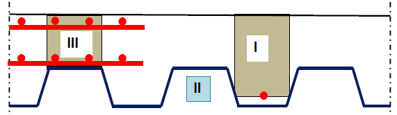 Figure 1
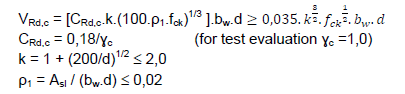
The first component is the concrete rib, area I. Traditionally the shear resistance is calculated based on the concrete rib without shear reinforcement in accordance with BS EN 1992-1-1; 6.2.2. For simplicity the actual cross-section of the rib is replaced by a rectangular cross-section of concrete with width equal to the average width of the rib and height equal to the distance between the either the profile centroid or rib reinforcement and the top of the concrete. For conformity with the Eurocodes it is necessary to use this model. The reinforcement is assumed to be fully anchored (100% effective). This is a more liberal assumption than in the BS EN 1992-1-1. On the other hand the contribution of the steel sheet is conservatively neglected.
Using this traditional method, in most composite slab cases, the profile itself is used to ‘activate’ the concrete rib. Any additional trough reinforcement required for say flexural enhancement does not give any more shear resistance contribution. This is because the rho1 value as given below usually exceeds the 0.02 limit even with just the profile cross section area itself.
However, when using the model, to activate all three components, rib reinforcement is needed to activate the concrete rib resistance which then allows the deck to also contribute.
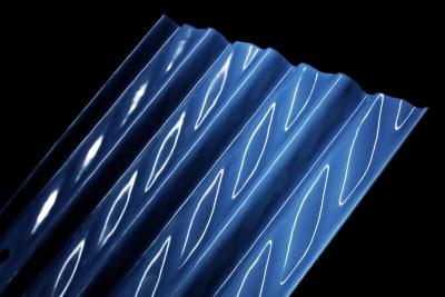
The second component shown as area II is the shear resistance generated from the decking profile which is not covered by BS EN 1992. Figure 2 shows the typical web geometry for our ComFlor® 60 profile. The model is based on the assumption that the contribution to the vertical shear resistance per web is equal to the vertical component of the shear yield resistance Vlu of the part of web between the radii (hℓ), so that Vlu = hℓ. tp. fy/√3. The additional contribution to the vertical shear resistance per m slab width is:
VRd,p = ((1000/300mm pitch) x 2 webs per rib) x Vlu x cos23°
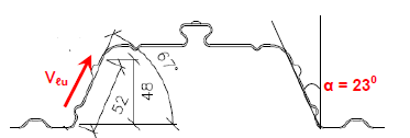
Figure 2
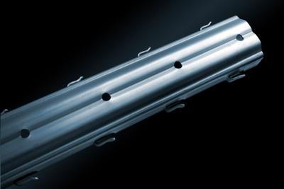
The third component is the additional shear resistance generated from the concrete above the flange of the deck between the concrete ribs, as shown in Figure 3, again, not covered by traditional BS EN 1992 method.

Figure 3
The shear resistance capacity of this particular area is calculated the same method as for the first component but by utilising a second layer of mesh. The conventional single mesh layer is generally required for anti-crack control, fire resistance, and composite beam requirements etc. The second layer is then required to activate the third component of concrete flange resistance.
The benefits for designers
The model shows that the rules in BS EN 1994 with the reference to BS EN 1992 do not give sufficient detailed information for a realistic determination of the vertical shear resistance. If for the ribs the rules in BS EN 1992 are applied with simplified assumption that the reinforcement is fully effective, the contribution to the vertical shear resistance is still underestimated. Use of rib reinforcement is essential for contribution of the rib, and that the steel deck gives a considerable contribution to the vertical shear resistance of the composite slab. As a result of the model, the vertical shear resistance of ComFlor® 60 for example can be increased by nearly 3.5-times as much as the traditional code calculation. This clearly demonstrates the advantages achieved using the latest ComFlor® 9 design software when required to deal with the above mentioned heavier loading requirements set by designers.
For further information on vertical shear resistance, please contact Mark Davies (BEng Hons MRes), Tata Steel:
T:+44 (0) 1244 892131
E: mark.r.davies@tatasteeleurope.com
OR
For information on our ComFlor® composite floor decking range, please contact:
T: +44 (0) 1244 892199