Durbar
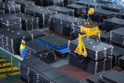
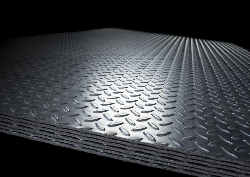
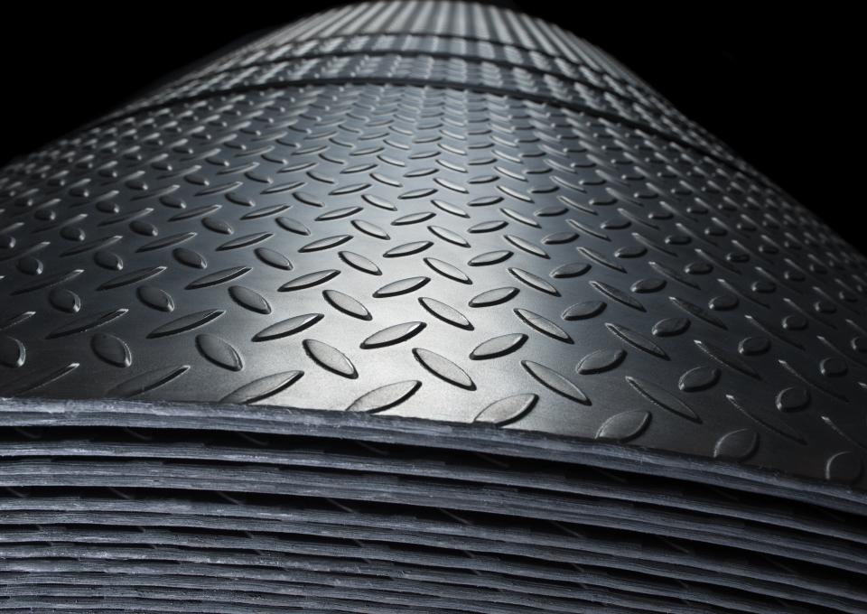
Durbar® is the leading brand of hot-rolled structural steel floor plate, made in the UK for over 50 years – only by Tata Steel. The pattern of diamond studs on genuine Durbar is on average 23% deeper than generic checker plates, with 10% more studs providing outstanding slip resistance.
Durbar is readily available: we are committed to prompt and reliable delivery. The consistent quality of Durbar offers reliable, repeatable processing. Its distinctive, raised surface pattern is extremely slip-resistant at all angles – allowing plates to be used in any direction. Its self-draining surface is easy to clean and reduces corrosion.
EN-Product-Hot-Rolled-Durbar floor plate-S235JR+AR TSUK
EN-Product-Hot-Rolled-Durbar floor plate-All grades OverviewTSUK
There is patterned steel floor plate - and there is Durbar® - Only by Tata Steel
Outstanding slip resistance
Slips and trips are the most common cause of injuries at work. Durbar’s unique pattern of raised studs has been proven, by external laboratory testing, to provide outstanding resistance to slip, in both dry and wet conditions.
Fire resistance
Fire resistance ratings are determined via testing, according to various standards (including but not limited to BS EN 13501-2, BS 476-21, BS 476-22 for the UK and EU). The regulations may require a specific application to be submitted for fire resistance testing. It is the responsibility of the customer to ensure that any form of construction which includes Durbar floor plate meets the required fire resistance rating.
Fire resistance ratings are required within buildings in many, but not all, situations; this includes load bearing elements of construction such as floors. These requirements vary for different scenarios and building purpose groups. Fire resistance ratings are not always required under certain circumstances, for example; platform floors, external horizontal and external vertical means of escape, and raised storage areas in single-storey buildings used for storage and industrial purposes do not always require fire resistance ratings in the UK.
The customer must satisfy themselves that they comply with the relevant national requirements for fire resistance ratings. These and any exclusions are detailed in Approved Document B (Fire safety) Volumes 1 and 2 for the UK.
Saving you money
Durbar's structural properties reduce cost by eliminating the need for separate structural and flooring components – a distinct advantage over other materials, such as aluminium.
Easy to clean, self-draining surface
Durbar's evenly distributed, raised stud pattern creates a self-draining surface which is easy to clean. The process of producing Durbar even produces an abrasion-resistant surface, giving it a long service life.
A sustainable choice
Durbar is produced in the UK to the highest standards, including BES 6001 for responsible sourcing which guarantees the integrity of the supply chain.
Quality, choice and availability
Durbar is certified to ISO TS 16949:2009 and meets the requirements of the Construction Products Directive. It is available in three different structural grades to fit your needs. Durbar is supplied via an extensive UK network of in-house and partner distributors.
Limitation of use statement
EN 10025-1:2004 CE Approved Factory Production Control Certificate
0038/CPD/20060004/A (Limitations of Use “Floor Plate Applications”).
Relationship with standards
Durbar meets the mechanical and chemical properties of EN 10025-2:2004
and is available in grades S235JR+AR, S275JR+AR and S355JR+AR.
Load span data
Members of The Steel Construction Institute can view load span data for Durbar at www.steelbiz.org, in table C242, floor plates simply supported, from the Steel Designers Manual, 6th Edition, 2003.
EN-Product-Hot-Rolled-Durbar floor plate-S235JR+AR-Properties1TSUK
Mechanical Properties
The mechanical properties of Durbar® comply with EN 10025-2: 2004 and are shown in the table below. The values shown for strength and elongation are for test pieces taken transverse to the rolling direction; those for the impact test are for test pieces taken in the rolling direction.
| Grade | S235JR+AR | |
|---|---|---|
| Min. yield strength1 ReL (N/mm2) | 235 | |
| Tensile strength Rm (N/mm2) | 360 - 510 | |
| Elongation % | 3 ≤ t ≤ 12.5 | 24 |
| Impact strength | Temp. °C | 20 |
| Min. energy J | 27 |
1. Lower yield strength or 0.2% proof stress applies.
t - material thickness in mm.
Impact tests can be performed for thicknesses ≥ 6.0mm. Please contact us for details.
Elongation after fracture A uses test piece length L0 = 5.65√S0.
Chemical composition
The chemical composition of Durbar complies with EN 10025-2:2004 and is shown in the table below.
| Grade | S235JR+AR | |
|---|---|---|
| C | Max. | 0.17 |
| Mn | Max. | 1.40 |
| P | Max. | 0.035 |
| S | Max. | 0.035 |
| Si | Max. | - |
| N | Max. | 0.012 |
All values in weight%.
EN-Product-Hot-Rolled-Durbar floor plate-S235JR+AR-DimensionsTSUK
Dimensions
Dimensions in mm.
| Thickness | Standard widths |
|---|---|
| Standard | S235JR+AR |
| 3 | 1000 / 1250 |
| 4.5 | 1000 / 1250 / 1500 |
| 6 | 1000 / 1250 / 1500 |
| 8 | 1000 / 1250 / 1500 |
| 10 | 1000 / 1250 / 1500 |
| 12.5 | 1000 / 1250 / 1500 |
The minimum width is 1000 mm. The maximum width is 1549mm.
Please contact us for details for any other non-standard dimensions.
Tolerances
Tolerances for wide strip and slit wide strip comply with standard EN 10051:2010.
Tighter tolerances are available, please contact us.
EN-Product-Hot-rolled-All grades Shape and dimensional tolerances TSUK
Shape and dimensional tolerances
The specified values for wide strip do not apply to the uncropped ends of the coil (‘head’ and ‘tail’). The length of these uncropped ends is calculated using the following formula:
length (in metres) = 90/nominal thickness (in mm), with a maximum of 20 metres.
If required, this part of the coil can be removed, however an additional cost may be charged for this.
Tolerances on thickness
Tata Steel can supply to full thickness tolerance specified in EN 10051:2010.
Tighter tolerances are available as shown below:
| Product family | Thickness tolerances available (% of full EN 10051:2010 tolerance) |
|||
|---|---|---|---|---|
| 100% | 75% | 66% | 50% | |
| Steel for forming | Yes | Yes | Yes | (see note 1) |
| High-strength low-alloy (HSLA) | Yes | Yes | Yes | Yes |
| AHSS | Yes | Yes | Yes | Yes |
| Structural steel | Yes | Yes | Yes | Yes |
| Boron manganese steel | Yes | Yes | Yes | |
| Steel for gas cylinders | Yes | |||
1 Please contact us for tolerances below 66%
Please contact us on the availability of special tolerances to meet your requirements.
Tolerances on thickness for hot-rolled steel with a low carbon content for cold forming
(DD11-DD14 in EN 10111:2008)
| Nominal thickness | Tolerances for a nominal width of | ||||
|---|---|---|---|---|---|
| ≤ 1200 | > 1200 | > 1500 | > 1800 | ||
| ≤ 1500 | ≤ 1800 | ||||
|
|
≤ 2.00 |
± 0.13 |
± 0.14 |
± 0.16 |
- |
|
> 2.00 |
≤ 2.50 |
± 0.14 |
± 0.16 |
± 0.17 |
± 0.19 |
|
> 2.50 |
≤ 3.00 |
± 0.15 |
± 0.17 |
± 0.18 |
± 0.20 |
|
> 3.00 |
≤ 4.00 |
± 0.17 |
± 0.18 |
± 0.20 |
± 0.20 |
|
> 4.00 |
≤ 5.00 |
± 0.18 |
± 0.20 |
± 0.21 |
± 0.22 |
|
> 5.00 |
≤ 6.00 |
± 0.20 |
± 0.21 |
± 0.22 |
± 0.23 |
|
> 6.00 |
≤ 8.00 |
± 0.22 |
± 0.23 |
± 0.23 |
± 0.26 |
|
> 8.00 |
≤ 11.00 |
± 0.24 |
± 0.25 |
± 0.25 |
± 0.28 |
All dimensions are mm.
Tolerances on thickness of steel grades with a specified minimum yield strength
Re ≤ 300 N/mm2 (category A)
| Nominal thickness | Tolerances for a nominal width of | ||||
|---|---|---|---|---|---|
| ≤ 1200 | > 1200 | > 1500 | > 1800 | ||
| ≤ 1500 | ≤ 1800 | ||||
|
≤ 2.00 |
± 0.17 |
± 0.19 |
± 0.21 |
- |
|
|
> 2.00 |
≤ 2.50 |
± 0.18 |
± 0.21 |
± 0.23 |
± 0.25 |
|
> 2.50 |
≤ 3.00 |
± 0.20 |
± 0.22 |
± 0.24 |
± 0.26 |
|
> 3.00 |
≤ 4.00 |
± 0.22 |
± 0.24 |
± 0.26 |
± 0.27 |
|
> 4.00 |
≤ 5.00 |
± 0.24 |
± 0.26 |
± 0.28 |
± 0.29 |
|
> 5.00 |
≤ 6.00 |
± 0.26 |
± 0.28 |
± 0.29 |
± 0.31 |
|
> 6.00 |
≤ 8.00 |
± 0.29 |
± 0.30 |
± 0.31 |
± 0.35 |
|
> 8.00 |
≤ 10.00 |
± 0.32 |
± 0.33 |
± 0.34 |
± 0.40 |
|
> 10.00 |
≤ 12.50 |
± 0.35 |
± 0.36 |
± 0.37 |
± 0.43 |
|
> 12.50 |
≤ 15.00 |
± 0.37 |
± 0.38 |
± 0.40 |
± 0.46 |
|
> 15.00 |
≤ 25.00 |
± 0.40 |
± 0.42 |
± 0.45 |
± 0.50 |
All dimensions are mm.
Tolerances on thickness of steel grades with a specified minimum yield strength
300 N/mm2 < Re ≤ 360 N/mm2 (category B)
| Nominal thickness | Tolerances for a nominal width of | ||||
|---|---|---|---|---|---|
| ≤ 1200 | > 1200 | > 1500 | > 1800 | ||
| ≤ 1500 | ≤ 1800 | ||||
|
|
≤ 2.00 |
± 0.20 |
± 0.22 |
± 0.24 |
- |
|
> 2.00 |
≤ 2.50 |
± 0.21 |
± 0.24 |
± 0.26 |
± 0.29 |
|
> 2.50 |
≤ 3.00 |
± 0.23 |
± 0.25 |
± 0.28 |
± 0.30 |
|
> 3.00 |
≤ 4.00 |
± 0.25 |
± 0.28 |
± 0.30 |
± 0.31 |
|
> 4.00 |
≤ 5.00 |
± 0.28 |
± 0.30 |
± 0.32 |
± 0.33 |
|
> 5.00 |
≤ 6.00 |
± 0.30 |
± 0.32 |
± 0.33 |
± 0.36 |
|
> 6.00 |
≤ 8.00 |
± 0.33 |
± 0.35 |
± 0.36 |
± 0.40 |
|
> 8.00 |
≤ 10.00 |
± 0.37 |
± 0.38 |
± 0.39 |
± 0.46 |
|
> 10.00 |
≤ 12.50 |
± 0.40 |
± 0.41 |
± 0.43 |
± 0.49 |
|
> 12.50 |
≤ 15.00 |
± 0.43 |
± 0.44 |
± 0.46 |
± 0.53 |
|
> 15.00 |
≤ 25.00 |
± 0.46 |
± 0.48 |
± 0.52 |
± 0.58 |
All dimensions are mm.
Tolerances on thickness of steel grades with a specified minimum yield strength
360 N/mm2 < Re ≤ 420 N/mm2 (category C)
| Nominal thickness |
Tolerances for a nominal width of |
||||
|---|---|---|---|---|---|
| ≤ 1200 | > 1200 | > 1500 | > 1800 | ||
| ≤ 1500 | ≤ 1800 | ||||
|
|
≤ 2.00 |
± 0.22 |
± 0.25 |
± 0.27 |
- |
|
> 2.00 |
≤ 2.50 |
± 0.23 |
± 0.27 |
± 0.30 |
± 0.33 |
|
> 2.50 |
≤ 3.00 |
± 0.26 |
± 0.29 |
± 0.31 |
± 0.34 |
|
> 3.00 |
≤ 4.00 |
± 0.29 |
± 0.31 |
± 0.34 |
± 0.35 |
|
> 4.00 |
≤ 5.00 |
± 0.31 |
± 0.34 |
± 0.36 |
± 0.38 |
|
> 5.00 |
≤ 6.00 |
± 0.34 |
± 0.36 |
± 0.38 |
± 0.40 |
|
> 6.00 |
≤ 8.00 |
± 0.38 |
± 0.39 |
± 0.40 |
± 0.46 |
|
> 8.00 |
≤ 10.00 |
± 0.42 |
± 0.43 |
± 0.44 |
± 0.52 |
|
> 10.00 |
≤ 12.50 |
± 0.46 |
± 0.47 |
± 0.48 |
± 0.56 |
|
> 12.50 |
≤ 15.00 |
± 0.48 |
± 0.49 |
± 0.52 |
± 0.60 |
|
> 15.00 |
≤ 25.00 |
± 0.52 |
± 0.55 |
± 0.59 |
± 0.65 |
All dimensions are mm.
Tolerances on thickness of steel grades with a specified minimum yield strength
420 N/mm2 < Re ≤ 900 N/mm2 (category D)
|
Nominal thickness |
Tolerances for a nominal width of | ||||
|---|---|---|---|---|---|
| ≤ 1200 | > 1200 | > 1500 | > 1800 | ||
| ≤ 1500 | ≤ 1800 | ||||
|
|
≤ 2.00 |
± 0.24 |
± 0.27 |
± 0.29 |
- |
|
> 2.00 |
≤ 2.50 |
± 0.25 |
± 0.29 |
± 0.32 |
± 0.35 |
|
> 2.50 |
≤ 3.00 |
± 0.28 |
± 0.31 |
± 0.34 |
± 0.36 |
|
> 3.00 |
≤ 4.00 |
± 0.31 |
± 0.34 |
± 0.36 |
± 0.38 |
|
> 4.00 |
≤ 5.00 |
± 0.34 |
± 0.36 |
± 0.39 |
± 0.41 |
|
> 5.00 |
≤ 6.00 |
± 0.36 |
± 0.39 |
± 0.41 |
± 0.43 |
|
> 6.00 |
≤ 8.00 |
± 0.41 |
± 0.42 |
± 0.43 |
± 0.49 |
|
> 8.00 |
≤ 10.00 |
± 0.45 |
± 0.46 |
± 0.48 |
± 0.56 |
|
> 10.00 |
≤ 12.50 |
± 0.49 |
± 0.50 |
± 0.52 |
± 0.60 |
|
> 12.50 |
≤ 15.00 |
± 0.52 |
± 0.53 |
± 0.56 |
± 0.64 |
|
> 15.00 |
≤ 25.00 |
± 0.56 |
± 0.59 |
± 0.63 |
± 0.70 |
All dimensions are mm.
Tolerances on width
Tolerances in mm.
| Nominal width w | ||||
|---|---|---|---|---|
| Mill edges | Trimmed edges | |||
| lower | upper | lower | upper | |
|
w ≤ 1200 |
0 |
20 |
0 |
3 |
|
1200 < w ≤ 1850 |
0 |
20 |
0 |
5 |
|
w > 1850 |
0 |
25 |
0 |
6 |
Tolerances in mm for wide strip and slit wide strip
The tolerances for wide strip and slit wide strip comply with standard EN 10051:2010.
The specified values for wide strip do not apply to the uncropped ends of the coil (‘head’ and ‘tail’). The length of these uncropped ends is calculated using the following formula:
length (in metres) = 90/nominal thickness (in mm), with a maximum of 20 metres.
If required, this part of the coil can be removed, however an additional cost may be charged for this.
Edge camber
The deviation from the edge over a length of 5000mm:
• with mill edges, no more than 20mm
• with trimmed edges, no more than 15mm
Flatness
Requirements as regards flatness can be agreed at the time of enquiry.
Option for maximum crown values
The following high crown C40 options available for hot-rolled products.
Crown values on the C20-position as well as minimum crown values on both C20 and C40 position are also available on request.
Maximum Crown C40 in µm values for hot-rolled steel with a low carbon content for cold forming
(DD11-DD14 in EN 10111:2008)
|
Category 1 |
C40 |
||||
|---|---|---|---|---|---|
| Nominal Thickness |
≤ 1200 |
> 1200 |
> 1500 |
> 1800 |
|
|
≤ 1500 |
≤ 1800 |
||||
|
> 1.47 |
≤ 2.00 |
40 |
40 |
40 |
40 |
|
> 2.00 |
≤ 2.50 |
40 |
40 |
50 |
50 |
|
> 2.50 |
≤ 3.00 |
40 |
40 |
50 |
50 |
|
> 3.00 |
≤ 6.00 |
40 |
50 |
50 |
50 |
|
> 6.00 |
≤ 11.00 |
50 |
50 |
50 |
50 |
Maximum Crown C40 in µm values of structural steel grades
(S185-S235-S275 ≤ 10mm in EN 10025-2:2004)
|
Category 2 |
C40 |
||||
|---|---|---|---|---|---|
| Nominal Thickness |
≤ 1200 |
> 1200 |
> 1500 |
> 1800 |
|
|
≤ 1500 |
≤ 1800 |
||||
|
> 1.47 |
≤ 2.00 |
40 |
40 |
40 |
40 |
|
> 2.00 |
≤ 2.50 |
40 |
40 |
50 |
50 |
|
> 2.50 |
≤ 20.00 |
50 |
50 |
50 |
50 |
Maximum Crown C40 in µm values of structural steel grades(S275 > 10mm in EN 10025-2:2004)
and HSLA grades (S315MC in EN 10149-2:1996)
|
Category 3 |
C40 |
||||
|---|---|---|---|---|---|
| Nominal Thickness |
≤ 1200 |
> 1200 |
> 1500 |
> 1800 |
|
|
≤ 1500 |
≤ 1800 |
||||
|
> 1.47 |
≤ 2.00 |
50 |
50 |
60 |
60 |
|
> 2.00 |
≤ 2.50 |
50 |
60 |
60 |
60 |
|
> 2.50 |
≤ 3.00 |
50 |
60 |
60 |
60 |
|
> 3.00 |
≤ 20.00 |
60 |
60 |
70 |
70 |
Maximum Crown C40 in µm values of HSLA grades
(S355MC, S420MC, S460MC, S500MC, S550MC in EN 10149-2:1996)
|
Category 4 |
C40 |
||||
|---|---|---|---|---|---|
| Nominal Thickness |
≤ 1200 |
> 1200 |
> 1500 |
> 1800 |
|
|
≤ 1500 |
≤ 1800 |
||||
|
> 1.47 |
≤ 2.00 |
60 |
70 |
70 |
70 |
|
> 2.00 |
≤ 2.50 |
60 |
70 |
80 |
80 |
|
> 2.50 |
≤ 3.00 |
60 |
70 |
80 |
80 |
|
> 3.00 |
≤ 5.00 |
70 |
70 |
80 |
80 |
|
> 5.00 |
≤ 20.00 |
80 |
80 |
80 |
80 |
Dimensions and coil weights
Tata Steel can supply hot-rolled steels with the following minimum and maximum dimensions and weights:
| Description | Availability |
|---|---|
| Coil diameter inner non-pickled | 762mm |
| Coil diameter inner pickled | 610mm standard |
| Tolerance on inner diameter | +0/-50mm |
| Coil diameter outer non-pickled | Outer diameter available is 10/7 x width |
| to reduce possibility of coil tipping over | |
| Max. 2200mm | |
| Min. 1050mm | |
| Coil diameter outer pickled and oiled | Outer diameter available is 10/7 x width |
| to reduce possibility of coil tipping over | |
| Outer diameter | |
| limit 2200mm | |
| Min. 1050mm | |
| Coil weight | Max. 32 tonnes |
| Additional maximum limits from transport | |
| limits and outer coil diameter | |
| Some HR products may have different | |
| coil weight ranges | |
| Minimum tonnage per order | Please refer to price list for order quantity details |
| Minimum order quantities may apply |
EN-Product-Hot-Rolled-Durbar floor plate-All grades Enquiry form TSUK
To submit an enquiry for Durbar floor plate, please contact connect.durbar@tatasteeleurope.com
EN-Product-Hot-Rolled-Durbar floor plate-All grades-Design TSUK
Using Durbar®
Durbar is a non-slip raised pattern floor plate of integral manufacture (the pattern is rolled in not welded). The "tear drop" studs are distributed to give maximum slip resistance in a variety of applications whilst ensuring a free draining surface.
The nominal gauge of Durbar is the thickness of the plain plate exclusive of pattern.
Unit Area Density
| Thickness on plain | Mass |
|---|---|
| (mm) | (kg/m2) |
| 3 | 26.83 |
| 4.5 | 38.59 |
| 6 | 50.36 |
| 8 | 66.04 |
| 10 | 81.73 |
|
12.5 |
101.34 |
Capacity Tables
It is usual to consider floor plates as supported on all four edges although stiffeners or joint covers may only support two edges. If the plates are securely bolted or welded to the supporting system, they may be considered as encastré. This increases the load carrying capacity slightly but reduces the deflection considerably.
The thickness given is exclusive of any raised pattern i.e. on plain.
The breadth is the smaller dimension and the length the greater, irrespective of the position of the main support members.
The maximum uniformly distributed load on the plate (w) is given by Pounder's formula and the maximum skin stress is limited to the design strength py
For calculating the maximum deflection (dmax) at serviceability, the uniformly distributed imposed load (wimp) on the plate is derived as follows.
w = gdead wdead + gimp wimp
wimp = (w - gdead wdead)/ gimp
For plates simply supported on all four edges
This formula assumes that there is no resistance to uplift at plate corners.
w = a1 py t2 / k B2 [ 1 + a2(1-k) + a3(1-k)2]
dmax = a4 k wimp B4 [1+a5(1-k) + a6(1-k)2] / E t3
Where resistance to uplift at corners is provided, the above formula will be conservative. Higher values may be obtained by assuming encastré status as outlined below.
For plates encastré on all four edges
The plate must be secured to prevent uplift, which would otherwise occur at the plate corners.
w = a7 py t2 / k B2 [ 1 + a8(1-k) + a9(1-k)2]
dmax = a10 k wimp B4 [1+a11(1-k) + a12(1-k)2] / E t3
Where:
L = length of plate (mm) (L > B)
B = breadth of plate (mm)
t = thickness of the plate on plain (mm)
k = L4/(L4+ B4)
py = design strength of plate ( 275 N/mm2 or 355 N/mm2)
E = Young's modulus (205 x 103 N/mm2)
1/m = Poisson's ratio (m = 3.0)
gdead = load factor for dead load (1.4)
gimp = load factor for imposed load (1.6)
dmax = maximum deflection (mm) at serviceability due to imposed loads only
w = uniformly distributed load on plate (ultimate) (N/mm2)
wdead = uniformly distributed self weight of plate (N/mm2)
wimp = uniformly distributed imposed load on plate (N/mm2)
a1 to a12 are constants as below:
| Constant | Value |
|---|---|
| a1 | = 4/3 |
| a2 | = 14/75 |
| a3 | = 20/57 |
| a4 | = (5m2 -5)/32m2 |
| a5 | = 37/175 |
| a6 | = 79/201 |
| a7 | = 2 |
| a8 | = 11/35 |
| a9 | = 79/141 |
| a10 | = (m2 -1)/32m2 |
| a11 | = 47/210 |
| a12 |
= 200/517 |
Durbar ultimate load capacity –various sized plates
Fixed on all four sides (encastré)
The ultimate uniformly distributed load for various sizes of Durbar plates fixed on all four sides and stressed to 275N/mm2 can be determined by using the table. The values are based upon equations developed by C.C. Pounder and conform to the construction and fixing requirements in BS 4592-5 : 2006. The values in the tables are theoretical; in-use performance may vary. This information should not be used without the advice of a qualified structural engineer. Users of this information should satisfy themselves that it is suitable for their purpose.
Ultimate load capacity (kN/m2) for Durbar fixed on all four sides and stressed to 275N/mm2
Values obtained with plates secured to prevent uplift
| Thickness (t) | Ultimate distributed load (kN/m2) for length, L, (mm) | ||||||||
|---|---|---|---|---|---|---|---|---|---|
| (mm) | Breadth, B, (mm) | 600 | 800 | 1000 | 1200† | 1400 † | 1600 † | 1800 † | 2000 † |
| 3 | 600 | 21.2 | 16.3 | 14.9 | 14.3 | 14.1 | 13.9 | 13.9 | 13.8 |
| 800 | 10.7§ | 8.4§ | 7.5§ | 7.1§ | 6.9§ | 6.8§ | 6.7§ | ||
| 1000 | 5.6§ | 4.6§ | 4.2§ | 3.9§ | 3.8§ | 3.7§ | |||
| 1200 | 3.4§ | 2.9§ | 2.6§ | 2.5§ | 2.4§ | ||||
| 1400 | 2.3§ | 2.0§ | 1.8§ | 1.7§ | |||||
| 4.5 | 600 | 47.7 | 36.8 | 33.5 | 32.2 | 31.6 | 31.4 | 31.2 | 31.1 |
| 800 | 26.8 | 21.5 | 19.5 | 18.6 | 18.1 | 17.9 | 17.7 | ||
| 1000 | 17.2 | 14.2 | 12.9 | 12.2 | 11.8 | 11.6 | |||
| 1200 | 10.8 § | 9.1 § | 8.2 § | 7.7 § | 7.4 § | ||||
| 1400 | 7.0 § | 6.0 § | 5.5 § | 5.1 § | |||||
| 6 | 600 | 84.8 | 65.4 | 59.5 | 57.3 | 56.2 | 55.7 | 55.5 | 55.3 |
| 800 | 47.7 | 38.3 | 34.7 | 33.1 | 32.2 | 31.7 | 31.5 | ||
| 1000 | 30.5 | 25.3 | 22.9 | 21.7 | 21.0 | 20.6 | |||
| 1200 | 21.2 | 18 | 16.3 | 15.4 | 14.9 | ||||
| 1400 | 15.6 | 13.4 | 12.3 | 11.6 | |||||
| 8 | 600 | 150.8 | 116.2 | 105.9 | 101.8 | 100 | 99.1 | 98.6 | 98.3 |
| 800 | 84.8 | 68.1 | 61.7 | 58.8 | 57.3 | 56.4 | 56.0 | ||
| 1000 | 54.3 | 44.9 | 40.7 | 38.6 | 37.4 | 36.7 | |||
| 1200 | 37.7 | 31.9 | 29.0 | 27.4 | 26.5 | ||||
| 1400 | 27.7 | 23.9 | 21.8 | 20.6 | |||||
| 10 | 600 | 235.5 | 181.5 | 165.4 | 159.1 | 156.2 | 154.8 | 154.1 | 153.6 |
| 800 | 132.5 | 106.4 | 96.4 | 91.8 | 89.5 | 88.2 | 87.4 | ||
| 1000 | 84.8 | 70.2 | 63.7 | 60.3 | 58.4 | 57.3 | |||
| 1200 | 58.9 | 49.9 | 45.4 | 42.9 | 41.3 | ||||
| 1400 | 43.3 | 37.3 | 34.1 | 32.2 | |||||
| 12.5 | 600 | 368.0 | 283.6 | 258.4 | 248.6 | 244.1 | 241.9 | 240.7 | 240.0 |
| 800 | 207.0 | 166.2 | 150.7 | 143.5 | 139.8 | 137.8 | 136.6 | ||
| 1000 | 132.5 | 109.7 | 99.5 | 94.2 | 91.2 | 89.5 | |||
| 1200 | 92.0 | 77.9 | 70.9 | 67.0 | 64.6 | ||||
| 1400 | 67.6 | 58.3 | 53.3 | 50.3 | |||||
†. Stiffeners should be considered for spans in excess of 1100mm to avoid excessive deflections.
§. Loads have been limited so that deflection ≤B/100 at serviceability, where serviceability is due to the imposed load only
Fire safety
Reaction to fire
Durbar hot-rolled steel floor plate is non-combustible and has a fire rating of A1 (and A1FL for flooring). This applies to both the UK and Europe. It qualifies as a Classification Without Further Testing (CWFT) material mentioned in Approved Document B (Fire safety) Volumes 1 and 2, and set out in EC Decision 96/603/EC. These materials have known behaviour during a fire, and therefore do not need to undergo additional testing.
A1 and A1FL are the highest ratings achievable; materials with these ratings are non-combustible and will not contribute to a fire through their own degradation, nor will they generate smoke or burning droplets during a fire.
Resistance to fire
Fire resistance ratings are determined via testing, according to various standards (including but not limited to BS EN 13501-2, BS 476-21, BS 476-22 for the UK and EU). The regulations may require a specific application to be submitted for fire resistance testing. It is the responsibility of the customer to ensure that any form of construction which includes Durbar floor plate meets the required fire resistance rating.
Fire resistance ratings are required within buildings in many, but not all, situations; this includes load bearing elements of construction such as floors. These requirements vary for different scenarios and building purpose groups. Fire resistance ratings are not always required under certain circumstances, for example; platform floors, external horizontal and external vertical means of escape, and raised storage areas in single-storey buildings used for storage and industrial purposes.
The customer must satisfy themselves that they comply with the relevant national requirements for fire resistance ratings. These and any exclusions are detailed in Approved Document B (Fire safety) Volumes 1 and 2 for the UK.
EN-Product-Hot-Rolled-Durbar floor plate-All grades-Proven slip-resistanceTSUK
Unique self-draining stud pattern provides a slip-resistant surface
Keeping you safe
According to the UK Health and Safety Executive (HSE), over a third of all major injuries reported in the UK each year are caused as a result of a slip or trip1. That amounts to 172,000 injuries to workers every year, not counting injuries to the general public.
Products that contribute to safer passage over surfaces, can reduce the risk of slips and trips, whether in permanent conditions, such as in factories, or temporary conditions, such as construction, building and planned maintenance.
The dense pattern of studs on Durbar creates a slip-resistant surface at all angles and allows plates to be used in any direction. Durbar has a unique diamond pattern which, on average, is 23% deeper and has 10% more studs than other generic steel floor plates.
Tested and trusted
In recent independent tests carried out on genuine Durbar floor plate, slip resistance was found to be consistently good, in both dry and wet conditions.
The UK HSE and the influential UK Slip Resistance Group (UKRSG) recommend the use of a pendulum test to measure the slip resistance of flooring products. This test is according to EN 13036-4. The pendulum test measures the dynamic coefficient of friction and is designed to replicate a pedestrian heel strike. This has been found to best simulate the most common cause of slips.
Independent tests on genuine Durbar using the pendulum tester according to EN 13036-4 have shown consistently goodresults in both wet and dry conditions2. The measured pendulum test value (PTV) in the wet condition of 46 represents a ‘Low’ slip potential, according to UKSRG guidelines, while in the dry condition, a PTV of 73 provides a classification of ‘Extremely low’ slip potential.
Comparative tests on generic floor plate adopting either ‘T’or ‘A’ patterns have shown that the unique pattern of studs on genuine Durbar results in the lowest all-round slip potential.
The actual slip resistance of Durbar or any other floor plate willdepend on real-life application and the environment in which it is used. Galvanising, painting or coating Durbar can influence the slip resistance.
Pendulum test comparison
The table below, taken from UKSRG guidance, represents the risk category for a reasonably active pedestrian between 18 and 60, walking in a straight line on a level surface.
| Pendulum Value | Potential for Slip |
|---|---|
| 0-24 | High |
| 25-35 | Moderate |
| 36-64 | Low |
| 65+ | Extremely Low |
| Item | Potential for Slip | Potential for Slip |
|---|---|---|
| Durbar® from Tata Steel | Extremely Low | Low |
| Generic Type `T` floor plate | Low | Low |
| Generic Type `A` floor plate | Low | Low |
1. UK Health & Safety Executive Statistics, 2017/18 ; non-fatal injuries to workers according to self-reported estimates from the Labour Force Surve
2. External laboratory results performed according to BS EN13036-4 BS7976 / UK Slip Resistance Group guidelines, Wessex Precision Instruments Ltd, July 2019
EN-Product-Hot-Rolled-Durbar floor plate-All grades-FAQsTSUK
Frequently Asked Questions (FAQs)
What is the fire resistance of Durbar?
Durbar hot rolled steel floor plate is classed as non-combustible. When subjected to extreme heat, Durbar has distinct advantages over some other flooring materials. At temperatures where aluminium alloys have already begun to melt, Durbar steel floor plate will still be supporting design loads. The fire performance of an assembly is specific to the construction of that assembly and so we strongly recommend you check your fire rating with a qualified fire engineer.
What is the slip resistance of Durbar?
Durbar has been tested to BS 7976-2:2002 for slip resistance and found to have Extremely Low slip potential in the dry state and Low slip potential even when wet. The unique Durbar pattern ensures this optimised slip resistance and in comparison tests, competitors’ floor plate products display a lower slip resistance.
Will galvanising and painting Durbar affect it’s characteristics?
Independent testing, in both wet and dry conditions in accordance with BS7976-2 assessed as-supplied Durbar as extremely low slip when dry, and low slip when wet. Moreover, Durbar is self-draining.
Galvanising and/or painting will alter the surface condition, and thus the slip resistance – we suggest you should consult the paint manufacturer for details of appropriate paint systems.
Can Tata Steel provide calculations for my specific use case of Durbar?
Durbar is stronger than ordinary mild steels, easily fabricated, and therefore well suited to performing a structural role efficiently. We provide load capacity tables for typical configurations of Durbar in the Design section of this web-page, which cover a range of representative cases. For specific use cases, we recommend that you consult an independent design engineer.
Can I buy individual sheets of Durbar from Tata Steel?
We manufacture Durbar in coil form and can supply both coil and cut sheet. We are the largest distributor in the UK of Durbar in a cut-sheet format. We supply Durbar sheet to an extensive range of local stockists that can provide product in appropriate sizes and quantities for specific end use requirements and projects
Is Durbar a sustainable choice?
Durbar is a structurally efficient choice for slip-resistant, hard-wearing and long-lasting flooring. Compared to some alternatives, less supporting structure is required. Durbar itself is 100% truly recyclable steel – indeed every sheet of Durbar includes a significant proportion of recycled steel.
Durbar has been in use in structures for over 50 years and remains the benchmark in textured floorplate in the UK – the ability to match the pattern with existing material in use makes it excellent for prolonging the life of existing structures.
EN-Product-Hot-Rolled-Durbar floor plate-All grades-Downloads TSUK
Download:
EN-EngineeringConstruction-Brochure-Durbar floor plate
Durbar floor plate brochure
EN-EngineeringConstruction-Certificate-Strip UK DoPs
Declaration of Performance (DoP) - Structural steel (produced in the UK)
EN-Product-Hot-Rolled-Durbar floor plate-S275JR+AR TSUK
EN-Product-Hot-Rolled-Durbar floor plate-All grades OverviewTSUK
There is patterned steel floor plate - and there is Durbar® - Only by Tata Steel
Outstanding slip resistance
Slips and trips are the most common cause of injuries at work. Durbar’s unique pattern of raised studs has been proven, by external laboratory testing, to provide outstanding resistance to slip, in both dry and wet conditions.
Fire resistance
Fire resistance ratings are determined via testing, according to various standards (including but not limited to BS EN 13501-2, BS 476-21, BS 476-22 for the UK and EU). The regulations may require a specific application to be submitted for fire resistance testing. It is the responsibility of the customer to ensure that any form of construction which includes Durbar floor plate meets the required fire resistance rating.
Fire resistance ratings are required within buildings in many, but not all, situations; this includes load bearing elements of construction such as floors. These requirements vary for different scenarios and building purpose groups. Fire resistance ratings are not always required under certain circumstances, for example; platform floors, external horizontal and external vertical means of escape, and raised storage areas in single-storey buildings used for storage and industrial purposes do not always require fire resistance ratings in the UK.
The customer must satisfy themselves that they comply with the relevant national requirements for fire resistance ratings. These and any exclusions are detailed in Approved Document B (Fire safety) Volumes 1 and 2 for the UK.
Saving you money
Durbar's structural properties reduce cost by eliminating the need for separate structural and flooring components – a distinct advantage over other materials, such as aluminium.
Easy to clean, self-draining surface
Durbar's evenly distributed, raised stud pattern creates a self-draining surface which is easy to clean. The process of producing Durbar even produces an abrasion-resistant surface, giving it a long service life.
A sustainable choice
Durbar is produced in the UK to the highest standards, including BES 6001 for responsible sourcing which guarantees the integrity of the supply chain.
Quality, choice and availability
Durbar is certified to ISO TS 16949:2009 and meets the requirements of the Construction Products Directive. It is available in three different structural grades to fit your needs. Durbar is supplied via an extensive UK network of in-house and partner distributors.
Limitation of use statement
EN 10025-1:2004 CE Approved Factory Production Control Certificate
0038/CPD/20060004/A (Limitations of Use “Floor Plate Applications”).
Relationship with standards
Durbar meets the mechanical and chemical properties of EN 10025-2:2004
and is available in grades S235JR+AR, S275JR+AR and S355JR+AR.
Load span data
Members of The Steel Construction Institute can view load span data for Durbar at www.steelbiz.org, in table C242, floor plates simply supported, from the Steel Designers Manual, 6th Edition, 2003.
EN-Product-Hot-Rolled-Durbar floor plate-S275JR+AR-PropertiesTSUK
Mechanical Properties
The mechanical properties of Durbar® comply with EN 10025-2: 2004 and are shown in the table below. The values shown for strength and elongation are for test pieces taken transverse to the rolling direction; those for the impact test are for test pieces taken in the rolling direction.
| Grade | S275JR+AR | |
|---|---|---|
| Min. yield strength1 ReL (N/mm2) | 275 | |
| Tensile strength Rm (N/mm2) | 410 - 560 | |
| Elongation % | 3 ≤ t ≤ 12.5 | 21 |
| Impact strength | Temp. °C | 20 |
| Min. energy J | 27 |
1. Lower yield strength or 0.2% proof stress applies.
t - material thickness in mm.
Impact tests can be performed for thicknesses ≥ 6.0 mm. Please contact us for details.
Elongation after fracture A uses test piece length L0 = 5.65√S0.
Chemical composition
The chemical composition of Durbar® complies with EN 10025-2:2004 and is shown in the table below.
| Grade | S275JR+AR | |
|---|---|---|
| C | Max. | 0.21 |
| Mn | Max. | 1.50 |
| P | Max. | 0.035 |
| S | Max. | 0.035 |
| Si | Max. | – |
| N | Max. | 0.012 |
All values in weight%.
EN-Product-Hot-Rolled-Durbar floor plate-S275JR+AR-DimensionsTSUK
Dimensions
Dimensions in mm.
| Thickness | Standard widths |
|---|---|
| Standard | S275JR+AR |
| 3 | 1000 / 1250 |
| 4.5 | 1000 / 1250 / 1500 |
| 6 | 1000 / 1250 / 1500 |
| 8 | 1000 / 1250 / 1500 |
| 10 | 1000 / 1250 / 1500 |
| 12.5 | 1000 / 1250 / 1500 |
The minimum width is 1000 mm. The maximum width is 1549mm.
Please contact us for details for any other non-standard dimensions.
Tolerances
Tolerances for wide strip and slit wide strip comply with standard EN 10051:2010.
Tighter tolerances are available, please contact us.
EN-Product-Hot-rolled-All grades Shape and dimensional tolerances TSUK
Shape and dimensional tolerances
The specified values for wide strip do not apply to the uncropped ends of the coil (‘head’ and ‘tail’). The length of these uncropped ends is calculated using the following formula:
length (in metres) = 90/nominal thickness (in mm), with a maximum of 20 metres.
If required, this part of the coil can be removed, however an additional cost may be charged for this.
Tolerances on thickness
Tata Steel can supply to full thickness tolerance specified in EN 10051:2010.
Tighter tolerances are available as shown below:
| Product family | Thickness tolerances available (% of full EN 10051:2010 tolerance) |
|||
|---|---|---|---|---|
| 100% | 75% | 66% | 50% | |
| Steel for forming | Yes | Yes | Yes | (see note 1) |
| High-strength low-alloy (HSLA) | Yes | Yes | Yes | Yes |
| AHSS | Yes | Yes | Yes | Yes |
| Structural steel | Yes | Yes | Yes | Yes |
| Boron manganese steel | Yes | Yes | Yes | |
| Steel for gas cylinders | Yes | |||
1 Please contact us for tolerances below 66%
Please contact us on the availability of special tolerances to meet your requirements.
Tolerances on thickness for hot-rolled steel with a low carbon content for cold forming
(DD11-DD14 in EN 10111:2008)
| Nominal thickness | Tolerances for a nominal width of | ||||
|---|---|---|---|---|---|
| ≤ 1200 | > 1200 | > 1500 | > 1800 | ||
| ≤ 1500 | ≤ 1800 | ||||
|
|
≤ 2.00 |
± 0.13 |
± 0.14 |
± 0.16 |
- |
|
> 2.00 |
≤ 2.50 |
± 0.14 |
± 0.16 |
± 0.17 |
± 0.19 |
|
> 2.50 |
≤ 3.00 |
± 0.15 |
± 0.17 |
± 0.18 |
± 0.20 |
|
> 3.00 |
≤ 4.00 |
± 0.17 |
± 0.18 |
± 0.20 |
± 0.20 |
|
> 4.00 |
≤ 5.00 |
± 0.18 |
± 0.20 |
± 0.21 |
± 0.22 |
|
> 5.00 |
≤ 6.00 |
± 0.20 |
± 0.21 |
± 0.22 |
± 0.23 |
|
> 6.00 |
≤ 8.00 |
± 0.22 |
± 0.23 |
± 0.23 |
± 0.26 |
|
> 8.00 |
≤ 11.00 |
± 0.24 |
± 0.25 |
± 0.25 |
± 0.28 |
All dimensions are mm.
Tolerances on thickness of steel grades with a specified minimum yield strength
Re ≤ 300 N/mm2 (category A)
| Nominal thickness | Tolerances for a nominal width of | ||||
|---|---|---|---|---|---|
| ≤ 1200 | > 1200 | > 1500 | > 1800 | ||
| ≤ 1500 | ≤ 1800 | ||||
|
≤ 2.00 |
± 0.17 |
± 0.19 |
± 0.21 |
- |
|
|
> 2.00 |
≤ 2.50 |
± 0.18 |
± 0.21 |
± 0.23 |
± 0.25 |
|
> 2.50 |
≤ 3.00 |
± 0.20 |
± 0.22 |
± 0.24 |
± 0.26 |
|
> 3.00 |
≤ 4.00 |
± 0.22 |
± 0.24 |
± 0.26 |
± 0.27 |
|
> 4.00 |
≤ 5.00 |
± 0.24 |
± 0.26 |
± 0.28 |
± 0.29 |
|
> 5.00 |
≤ 6.00 |
± 0.26 |
± 0.28 |
± 0.29 |
± 0.31 |
|
> 6.00 |
≤ 8.00 |
± 0.29 |
± 0.30 |
± 0.31 |
± 0.35 |
|
> 8.00 |
≤ 10.00 |
± 0.32 |
± 0.33 |
± 0.34 |
± 0.40 |
|
> 10.00 |
≤ 12.50 |
± 0.35 |
± 0.36 |
± 0.37 |
± 0.43 |
|
> 12.50 |
≤ 15.00 |
± 0.37 |
± 0.38 |
± 0.40 |
± 0.46 |
|
> 15.00 |
≤ 25.00 |
± 0.40 |
± 0.42 |
± 0.45 |
± 0.50 |
All dimensions are mm.
Tolerances on thickness of steel grades with a specified minimum yield strength
300 N/mm2 < Re ≤ 360 N/mm2 (category B)
| Nominal thickness | Tolerances for a nominal width of | ||||
|---|---|---|---|---|---|
| ≤ 1200 | > 1200 | > 1500 | > 1800 | ||
| ≤ 1500 | ≤ 1800 | ||||
|
|
≤ 2.00 |
± 0.20 |
± 0.22 |
± 0.24 |
- |
|
> 2.00 |
≤ 2.50 |
± 0.21 |
± 0.24 |
± 0.26 |
± 0.29 |
|
> 2.50 |
≤ 3.00 |
± 0.23 |
± 0.25 |
± 0.28 |
± 0.30 |
|
> 3.00 |
≤ 4.00 |
± 0.25 |
± 0.28 |
± 0.30 |
± 0.31 |
|
> 4.00 |
≤ 5.00 |
± 0.28 |
± 0.30 |
± 0.32 |
± 0.33 |
|
> 5.00 |
≤ 6.00 |
± 0.30 |
± 0.32 |
± 0.33 |
± 0.36 |
|
> 6.00 |
≤ 8.00 |
± 0.33 |
± 0.35 |
± 0.36 |
± 0.40 |
|
> 8.00 |
≤ 10.00 |
± 0.37 |
± 0.38 |
± 0.39 |
± 0.46 |
|
> 10.00 |
≤ 12.50 |
± 0.40 |
± 0.41 |
± 0.43 |
± 0.49 |
|
> 12.50 |
≤ 15.00 |
± 0.43 |
± 0.44 |
± 0.46 |
± 0.53 |
|
> 15.00 |
≤ 25.00 |
± 0.46 |
± 0.48 |
± 0.52 |
± 0.58 |
All dimensions are mm.
Tolerances on thickness of steel grades with a specified minimum yield strength
360 N/mm2 < Re ≤ 420 N/mm2 (category C)
| Nominal thickness |
Tolerances for a nominal width of |
||||
|---|---|---|---|---|---|
| ≤ 1200 | > 1200 | > 1500 | > 1800 | ||
| ≤ 1500 | ≤ 1800 | ||||
|
|
≤ 2.00 |
± 0.22 |
± 0.25 |
± 0.27 |
- |
|
> 2.00 |
≤ 2.50 |
± 0.23 |
± 0.27 |
± 0.30 |
± 0.33 |
|
> 2.50 |
≤ 3.00 |
± 0.26 |
± 0.29 |
± 0.31 |
± 0.34 |
|
> 3.00 |
≤ 4.00 |
± 0.29 |
± 0.31 |
± 0.34 |
± 0.35 |
|
> 4.00 |
≤ 5.00 |
± 0.31 |
± 0.34 |
± 0.36 |
± 0.38 |
|
> 5.00 |
≤ 6.00 |
± 0.34 |
± 0.36 |
± 0.38 |
± 0.40 |
|
> 6.00 |
≤ 8.00 |
± 0.38 |
± 0.39 |
± 0.40 |
± 0.46 |
|
> 8.00 |
≤ 10.00 |
± 0.42 |
± 0.43 |
± 0.44 |
± 0.52 |
|
> 10.00 |
≤ 12.50 |
± 0.46 |
± 0.47 |
± 0.48 |
± 0.56 |
|
> 12.50 |
≤ 15.00 |
± 0.48 |
± 0.49 |
± 0.52 |
± 0.60 |
|
> 15.00 |
≤ 25.00 |
± 0.52 |
± 0.55 |
± 0.59 |
± 0.65 |
All dimensions are mm.
Tolerances on thickness of steel grades with a specified minimum yield strength
420 N/mm2 < Re ≤ 900 N/mm2 (category D)
|
Nominal thickness |
Tolerances for a nominal width of | ||||
|---|---|---|---|---|---|
| ≤ 1200 | > 1200 | > 1500 | > 1800 | ||
| ≤ 1500 | ≤ 1800 | ||||
|
|
≤ 2.00 |
± 0.24 |
± 0.27 |
± 0.29 |
- |
|
> 2.00 |
≤ 2.50 |
± 0.25 |
± 0.29 |
± 0.32 |
± 0.35 |
|
> 2.50 |
≤ 3.00 |
± 0.28 |
± 0.31 |
± 0.34 |
± 0.36 |
|
> 3.00 |
≤ 4.00 |
± 0.31 |
± 0.34 |
± 0.36 |
± 0.38 |
|
> 4.00 |
≤ 5.00 |
± 0.34 |
± 0.36 |
± 0.39 |
± 0.41 |
|
> 5.00 |
≤ 6.00 |
± 0.36 |
± 0.39 |
± 0.41 |
± 0.43 |
|
> 6.00 |
≤ 8.00 |
± 0.41 |
± 0.42 |
± 0.43 |
± 0.49 |
|
> 8.00 |
≤ 10.00 |
± 0.45 |
± 0.46 |
± 0.48 |
± 0.56 |
|
> 10.00 |
≤ 12.50 |
± 0.49 |
± 0.50 |
± 0.52 |
± 0.60 |
|
> 12.50 |
≤ 15.00 |
± 0.52 |
± 0.53 |
± 0.56 |
± 0.64 |
|
> 15.00 |
≤ 25.00 |
± 0.56 |
± 0.59 |
± 0.63 |
± 0.70 |
All dimensions are mm.
Tolerances on width
Tolerances in mm.
| Nominal width w | ||||
|---|---|---|---|---|
| Mill edges | Trimmed edges | |||
| lower | upper | lower | upper | |
|
w ≤ 1200 |
0 |
20 |
0 |
3 |
|
1200 < w ≤ 1850 |
0 |
20 |
0 |
5 |
|
w > 1850 |
0 |
25 |
0 |
6 |
Tolerances in mm for wide strip and slit wide strip
The tolerances for wide strip and slit wide strip comply with standard EN 10051:2010.
The specified values for wide strip do not apply to the uncropped ends of the coil (‘head’ and ‘tail’). The length of these uncropped ends is calculated using the following formula:
length (in metres) = 90/nominal thickness (in mm), with a maximum of 20 metres.
If required, this part of the coil can be removed, however an additional cost may be charged for this.
Edge camber
The deviation from the edge over a length of 5000mm:
• with mill edges, no more than 20mm
• with trimmed edges, no more than 15mm
Flatness
Requirements as regards flatness can be agreed at the time of enquiry.
Option for maximum crown values
The following high crown C40 options available for hot-rolled products.
Crown values on the C20-position as well as minimum crown values on both C20 and C40 position are also available on request.
Maximum Crown C40 in µm values for hot-rolled steel with a low carbon content for cold forming
(DD11-DD14 in EN 10111:2008)
|
Category 1 |
C40 |
||||
|---|---|---|---|---|---|
| Nominal Thickness |
≤ 1200 |
> 1200 |
> 1500 |
> 1800 |
|
|
≤ 1500 |
≤ 1800 |
||||
|
> 1.47 |
≤ 2.00 |
40 |
40 |
40 |
40 |
|
> 2.00 |
≤ 2.50 |
40 |
40 |
50 |
50 |
|
> 2.50 |
≤ 3.00 |
40 |
40 |
50 |
50 |
|
> 3.00 |
≤ 6.00 |
40 |
50 |
50 |
50 |
|
> 6.00 |
≤ 11.00 |
50 |
50 |
50 |
50 |
Maximum Crown C40 in µm values of structural steel grades
(S185-S235-S275 ≤ 10mm in EN 10025-2:2004)
|
Category 2 |
C40 |
||||
|---|---|---|---|---|---|
| Nominal Thickness |
≤ 1200 |
> 1200 |
> 1500 |
> 1800 |
|
|
≤ 1500 |
≤ 1800 |
||||
|
> 1.47 |
≤ 2.00 |
40 |
40 |
40 |
40 |
|
> 2.00 |
≤ 2.50 |
40 |
40 |
50 |
50 |
|
> 2.50 |
≤ 20.00 |
50 |
50 |
50 |
50 |
Maximum Crown C40 in µm values of structural steel grades(S275 > 10mm in EN 10025-2:2004)
and HSLA grades (S315MC in EN 10149-2:1996)
|
Category 3 |
C40 |
||||
|---|---|---|---|---|---|
| Nominal Thickness |
≤ 1200 |
> 1200 |
> 1500 |
> 1800 |
|
|
≤ 1500 |
≤ 1800 |
||||
|
> 1.47 |
≤ 2.00 |
50 |
50 |
60 |
60 |
|
> 2.00 |
≤ 2.50 |
50 |
60 |
60 |
60 |
|
> 2.50 |
≤ 3.00 |
50 |
60 |
60 |
60 |
|
> 3.00 |
≤ 20.00 |
60 |
60 |
70 |
70 |
Maximum Crown C40 in µm values of HSLA grades
(S355MC, S420MC, S460MC, S500MC, S550MC in EN 10149-2:1996)
|
Category 4 |
C40 |
||||
|---|---|---|---|---|---|
| Nominal Thickness |
≤ 1200 |
> 1200 |
> 1500 |
> 1800 |
|
|
≤ 1500 |
≤ 1800 |
||||
|
> 1.47 |
≤ 2.00 |
60 |
70 |
70 |
70 |
|
> 2.00 |
≤ 2.50 |
60 |
70 |
80 |
80 |
|
> 2.50 |
≤ 3.00 |
60 |
70 |
80 |
80 |
|
> 3.00 |
≤ 5.00 |
70 |
70 |
80 |
80 |
|
> 5.00 |
≤ 20.00 |
80 |
80 |
80 |
80 |
Dimensions and coil weights
Tata Steel can supply hot-rolled steels with the following minimum and maximum dimensions and weights:
| Description | Availability |
|---|---|
| Coil diameter inner non-pickled | 762mm |
| Coil diameter inner pickled | 610mm standard |
| Tolerance on inner diameter | +0/-50mm |
| Coil diameter outer non-pickled | Outer diameter available is 10/7 x width |
| to reduce possibility of coil tipping over | |
| Max. 2200mm | |
| Min. 1050mm | |
| Coil diameter outer pickled and oiled | Outer diameter available is 10/7 x width |
| to reduce possibility of coil tipping over | |
| Outer diameter | |
| limit 2200mm | |
| Min. 1050mm | |
| Coil weight | Max. 32 tonnes |
| Additional maximum limits from transport | |
| limits and outer coil diameter | |
| Some HR products may have different | |
| coil weight ranges | |
| Minimum tonnage per order | Please refer to price list for order quantity details |
| Minimum order quantities may apply |
EN-Product-Hot-Rolled-Durbar floor plate-All grades Enquiry form TSUK
To submit an enquiry for Durbar floor plate, please contact connect.durbar@tatasteeleurope.com
EN-Product-Hot-Rolled-Durbar floor plate-All grades-Design TSUK
Using Durbar®
Durbar is a non-slip raised pattern floor plate of integral manufacture (the pattern is rolled in not welded). The "tear drop" studs are distributed to give maximum slip resistance in a variety of applications whilst ensuring a free draining surface.
The nominal gauge of Durbar is the thickness of the plain plate exclusive of pattern.
Unit Area Density
| Thickness on plain | Mass |
|---|---|
| (mm) | (kg/m2) |
| 3 | 26.83 |
| 4.5 | 38.59 |
| 6 | 50.36 |
| 8 | 66.04 |
| 10 | 81.73 |
|
12.5 |
101.34 |
Capacity Tables
It is usual to consider floor plates as supported on all four edges although stiffeners or joint covers may only support two edges. If the plates are securely bolted or welded to the supporting system, they may be considered as encastré. This increases the load carrying capacity slightly but reduces the deflection considerably.
The thickness given is exclusive of any raised pattern i.e. on plain.
The breadth is the smaller dimension and the length the greater, irrespective of the position of the main support members.
The maximum uniformly distributed load on the plate (w) is given by Pounder's formula and the maximum skin stress is limited to the design strength py
For calculating the maximum deflection (dmax) at serviceability, the uniformly distributed imposed load (wimp) on the plate is derived as follows.
w = gdead wdead + gimp wimp
wimp = (w - gdead wdead)/ gimp
For plates simply supported on all four edges
This formula assumes that there is no resistance to uplift at plate corners.
w = a1 py t2 / k B2 [ 1 + a2(1-k) + a3(1-k)2]
dmax = a4 k wimp B4 [1+a5(1-k) + a6(1-k)2] / E t3
Where resistance to uplift at corners is provided, the above formula will be conservative. Higher values may be obtained by assuming encastré status as outlined below.
For plates encastré on all four edges
The plate must be secured to prevent uplift, which would otherwise occur at the plate corners.
w = a7 py t2 / k B2 [ 1 + a8(1-k) + a9(1-k)2]
dmax = a10 k wimp B4 [1+a11(1-k) + a12(1-k)2] / E t3
Where:
L = length of plate (mm) (L > B)
B = breadth of plate (mm)
t = thickness of the plate on plain (mm)
k = L4/(L4+ B4)
py = design strength of plate ( 275 N/mm2 or 355 N/mm2)
E = Young's modulus (205 x 103 N/mm2)
1/m = Poisson's ratio (m = 3.0)
gdead = load factor for dead load (1.4)
gimp = load factor for imposed load (1.6)
dmax = maximum deflection (mm) at serviceability due to imposed loads only
w = uniformly distributed load on plate (ultimate) (N/mm2)
wdead = uniformly distributed self weight of plate (N/mm2)
wimp = uniformly distributed imposed load on plate (N/mm2)
a1 to a12 are constants as below:
| Constant | Value |
|---|---|
| a1 | = 4/3 |
| a2 | = 14/75 |
| a3 | = 20/57 |
| a4 | = (5m2 -5)/32m2 |
| a5 | = 37/175 |
| a6 | = 79/201 |
| a7 | = 2 |
| a8 | = 11/35 |
| a9 | = 79/141 |
| a10 | = (m2 -1)/32m2 |
| a11 | = 47/210 |
| a12 |
= 200/517 |
Durbar ultimate load capacity –various sized plates
Fixed on all four sides (encastré)
The ultimate uniformly distributed load for various sizes of Durbar plates fixed on all four sides and stressed to 275N/mm2 can be determined by using the table. The values are based upon equations developed by C.C. Pounder and conform to the construction and fixing requirements in BS 4592-5 : 2006. The values in the tables are theoretical; in-use performance may vary. This information should not be used without the advice of a qualified structural engineer. Users of this information should satisfy themselves that it is suitable for their purpose.
Ultimate load capacity (kN/m2) for Durbar fixed on all four sides and stressed to 275N/mm2
Values obtained with plates secured to prevent uplift
| Thickness (t) | Ultimate distributed load (kN/m2) for length, L, (mm) | ||||||||
|---|---|---|---|---|---|---|---|---|---|
| (mm) | Breadth, B, (mm) | 600 | 800 | 1000 | 1200† | 1400 † | 1600 † | 1800 † | 2000 † |
| 3 | 600 | 21.2 | 16.3 | 14.9 | 14.3 | 14.1 | 13.9 | 13.9 | 13.8 |
| 800 | 10.7§ | 8.4§ | 7.5§ | 7.1§ | 6.9§ | 6.8§ | 6.7§ | ||
| 1000 | 5.6§ | 4.6§ | 4.2§ | 3.9§ | 3.8§ | 3.7§ | |||
| 1200 | 3.4§ | 2.9§ | 2.6§ | 2.5§ | 2.4§ | ||||
| 1400 | 2.3§ | 2.0§ | 1.8§ | 1.7§ | |||||
| 4.5 | 600 | 47.7 | 36.8 | 33.5 | 32.2 | 31.6 | 31.4 | 31.2 | 31.1 |
| 800 | 26.8 | 21.5 | 19.5 | 18.6 | 18.1 | 17.9 | 17.7 | ||
| 1000 | 17.2 | 14.2 | 12.9 | 12.2 | 11.8 | 11.6 | |||
| 1200 | 10.8 § | 9.1 § | 8.2 § | 7.7 § | 7.4 § | ||||
| 1400 | 7.0 § | 6.0 § | 5.5 § | 5.1 § | |||||
| 6 | 600 | 84.8 | 65.4 | 59.5 | 57.3 | 56.2 | 55.7 | 55.5 | 55.3 |
| 800 | 47.7 | 38.3 | 34.7 | 33.1 | 32.2 | 31.7 | 31.5 | ||
| 1000 | 30.5 | 25.3 | 22.9 | 21.7 | 21.0 | 20.6 | |||
| 1200 | 21.2 | 18 | 16.3 | 15.4 | 14.9 | ||||
| 1400 | 15.6 | 13.4 | 12.3 | 11.6 | |||||
| 8 | 600 | 150.8 | 116.2 | 105.9 | 101.8 | 100 | 99.1 | 98.6 | 98.3 |
| 800 | 84.8 | 68.1 | 61.7 | 58.8 | 57.3 | 56.4 | 56.0 | ||
| 1000 | 54.3 | 44.9 | 40.7 | 38.6 | 37.4 | 36.7 | |||
| 1200 | 37.7 | 31.9 | 29.0 | 27.4 | 26.5 | ||||
| 1400 | 27.7 | 23.9 | 21.8 | 20.6 | |||||
| 10 | 600 | 235.5 | 181.5 | 165.4 | 159.1 | 156.2 | 154.8 | 154.1 | 153.6 |
| 800 | 132.5 | 106.4 | 96.4 | 91.8 | 89.5 | 88.2 | 87.4 | ||
| 1000 | 84.8 | 70.2 | 63.7 | 60.3 | 58.4 | 57.3 | |||
| 1200 | 58.9 | 49.9 | 45.4 | 42.9 | 41.3 | ||||
| 1400 | 43.3 | 37.3 | 34.1 | 32.2 | |||||
| 12.5 | 600 | 368.0 | 283.6 | 258.4 | 248.6 | 244.1 | 241.9 | 240.7 | 240.0 |
| 800 | 207.0 | 166.2 | 150.7 | 143.5 | 139.8 | 137.8 | 136.6 | ||
| 1000 | 132.5 | 109.7 | 99.5 | 94.2 | 91.2 | 89.5 | |||
| 1200 | 92.0 | 77.9 | 70.9 | 67.0 | 64.6 | ||||
| 1400 | 67.6 | 58.3 | 53.3 | 50.3 | |||||
†. Stiffeners should be considered for spans in excess of 1100mm to avoid excessive deflections.
§. Loads have been limited so that deflection ≤B/100 at serviceability, where serviceability is due to the imposed load only
Fire safety
Reaction to fire
Durbar hot-rolled steel floor plate is non-combustible and has a fire rating of A1 (and A1FL for flooring). This applies to both the UK and Europe. It qualifies as a Classification Without Further Testing (CWFT) material mentioned in Approved Document B (Fire safety) Volumes 1 and 2, and set out in EC Decision 96/603/EC. These materials have known behaviour during a fire, and therefore do not need to undergo additional testing.
A1 and A1FL are the highest ratings achievable; materials with these ratings are non-combustible and will not contribute to a fire through their own degradation, nor will they generate smoke or burning droplets during a fire.
Resistance to fire
Fire resistance ratings are determined via testing, according to various standards (including but not limited to BS EN 13501-2, BS 476-21, BS 476-22 for the UK and EU). The regulations may require a specific application to be submitted for fire resistance testing. It is the responsibility of the customer to ensure that any form of construction which includes Durbar floor plate meets the required fire resistance rating.
Fire resistance ratings are required within buildings in many, but not all, situations; this includes load bearing elements of construction such as floors. These requirements vary for different scenarios and building purpose groups. Fire resistance ratings are not always required under certain circumstances, for example; platform floors, external horizontal and external vertical means of escape, and raised storage areas in single-storey buildings used for storage and industrial purposes.
The customer must satisfy themselves that they comply with the relevant national requirements for fire resistance ratings. These and any exclusions are detailed in Approved Document B (Fire safety) Volumes 1 and 2 for the UK.
EN-Product-Hot-Rolled-Durbar floor plate-All grades-Proven slip-resistanceTSUK
Unique self-draining stud pattern provides a slip-resistant surface
Keeping you safe
According to the UK Health and Safety Executive (HSE), over a third of all major injuries reported in the UK each year are caused as a result of a slip or trip1. That amounts to 172,000 injuries to workers every year, not counting injuries to the general public.
Products that contribute to safer passage over surfaces, can reduce the risk of slips and trips, whether in permanent conditions, such as in factories, or temporary conditions, such as construction, building and planned maintenance.
The dense pattern of studs on Durbar creates a slip-resistant surface at all angles and allows plates to be used in any direction. Durbar has a unique diamond pattern which, on average, is 23% deeper and has 10% more studs than other generic steel floor plates.
Tested and trusted
In recent independent tests carried out on genuine Durbar floor plate, slip resistance was found to be consistently good, in both dry and wet conditions.
The UK HSE and the influential UK Slip Resistance Group (UKRSG) recommend the use of a pendulum test to measure the slip resistance of flooring products. This test is according to EN 13036-4. The pendulum test measures the dynamic coefficient of friction and is designed to replicate a pedestrian heel strike. This has been found to best simulate the most common cause of slips.
Independent tests on genuine Durbar using the pendulum tester according to EN 13036-4 have shown consistently goodresults in both wet and dry conditions2. The measured pendulum test value (PTV) in the wet condition of 46 represents a ‘Low’ slip potential, according to UKSRG guidelines, while in the dry condition, a PTV of 73 provides a classification of ‘Extremely low’ slip potential.
Comparative tests on generic floor plate adopting either ‘T’or ‘A’ patterns have shown that the unique pattern of studs on genuine Durbar results in the lowest all-round slip potential.
The actual slip resistance of Durbar or any other floor plate willdepend on real-life application and the environment in which it is used. Galvanising, painting or coating Durbar can influence the slip resistance.
Pendulum test comparison
The table below, taken from UKSRG guidance, represents the risk category for a reasonably active pedestrian between 18 and 60, walking in a straight line on a level surface.
| Pendulum Value | Potential for Slip |
|---|---|
| 0-24 | High |
| 25-35 | Moderate |
| 36-64 | Low |
| 65+ | Extremely Low |
| Item | Potential for Slip | Potential for Slip |
|---|---|---|
| Durbar® from Tata Steel | Extremely Low | Low |
| Generic Type `T` floor plate | Low | Low |
| Generic Type `A` floor plate | Low | Low |
1. UK Health & Safety Executive Statistics, 2017/18 ; non-fatal injuries to workers according to self-reported estimates from the Labour Force Surve
2. External laboratory results performed according to BS EN13036-4 BS7976 / UK Slip Resistance Group guidelines, Wessex Precision Instruments Ltd, July 2019
EN-Product-Hot-Rolled-Durbar floor plate-All grades-FAQsTSUK
Frequently Asked Questions (FAQs)
What is the fire resistance of Durbar?
Durbar hot rolled steel floor plate is classed as non-combustible. When subjected to extreme heat, Durbar has distinct advantages over some other flooring materials. At temperatures where aluminium alloys have already begun to melt, Durbar steel floor plate will still be supporting design loads. The fire performance of an assembly is specific to the construction of that assembly and so we strongly recommend you check your fire rating with a qualified fire engineer.
What is the slip resistance of Durbar?
Durbar has been tested to BS 7976-2:2002 for slip resistance and found to have Extremely Low slip potential in the dry state and Low slip potential even when wet. The unique Durbar pattern ensures this optimised slip resistance and in comparison tests, competitors’ floor plate products display a lower slip resistance.
Will galvanising and painting Durbar affect it’s characteristics?
Independent testing, in both wet and dry conditions in accordance with BS7976-2 assessed as-supplied Durbar as extremely low slip when dry, and low slip when wet. Moreover, Durbar is self-draining.
Galvanising and/or painting will alter the surface condition, and thus the slip resistance – we suggest you should consult the paint manufacturer for details of appropriate paint systems.
Can Tata Steel provide calculations for my specific use case of Durbar?
Durbar is stronger than ordinary mild steels, easily fabricated, and therefore well suited to performing a structural role efficiently. We provide load capacity tables for typical configurations of Durbar in the Design section of this web-page, which cover a range of representative cases. For specific use cases, we recommend that you consult an independent design engineer.
Can I buy individual sheets of Durbar from Tata Steel?
We manufacture Durbar in coil form and can supply both coil and cut sheet. We are the largest distributor in the UK of Durbar in a cut-sheet format. We supply Durbar sheet to an extensive range of local stockists that can provide product in appropriate sizes and quantities for specific end use requirements and projects
Is Durbar a sustainable choice?
Durbar is a structurally efficient choice for slip-resistant, hard-wearing and long-lasting flooring. Compared to some alternatives, less supporting structure is required. Durbar itself is 100% truly recyclable steel – indeed every sheet of Durbar includes a significant proportion of recycled steel.
Durbar has been in use in structures for over 50 years and remains the benchmark in textured floorplate in the UK – the ability to match the pattern with existing material in use makes it excellent for prolonging the life of existing structures.
EN-Product-Hot-Rolled-Durbar floor plate-All grades-Downloads TSUK
Download:
EN-EngineeringConstruction-Brochure-Durbar floor plate
Durbar floor plate brochure
EN-EngineeringConstruction-Certificate-Strip UK DoPs
Declaration of Performance (DoP) - Structural steel (produced in the UK)
EN-Product-Hot-Rolled-Durbar floor plate-S355JR+AR TSUK
EN-Product-Hot-Rolled-Durbar floor plate-All grades OverviewTSUK
There is patterned steel floor plate - and there is Durbar® - Only by Tata Steel
Outstanding slip resistance
Slips and trips are the most common cause of injuries at work. Durbar’s unique pattern of raised studs has been proven, by external laboratory testing, to provide outstanding resistance to slip, in both dry and wet conditions.
Fire resistance
Fire resistance ratings are determined via testing, according to various standards (including but not limited to BS EN 13501-2, BS 476-21, BS 476-22 for the UK and EU). The regulations may require a specific application to be submitted for fire resistance testing. It is the responsibility of the customer to ensure that any form of construction which includes Durbar floor plate meets the required fire resistance rating.
Fire resistance ratings are required within buildings in many, but not all, situations; this includes load bearing elements of construction such as floors. These requirements vary for different scenarios and building purpose groups. Fire resistance ratings are not always required under certain circumstances, for example; platform floors, external horizontal and external vertical means of escape, and raised storage areas in single-storey buildings used for storage and industrial purposes do not always require fire resistance ratings in the UK.
The customer must satisfy themselves that they comply with the relevant national requirements for fire resistance ratings. These and any exclusions are detailed in Approved Document B (Fire safety) Volumes 1 and 2 for the UK.
Saving you money
Durbar's structural properties reduce cost by eliminating the need for separate structural and flooring components – a distinct advantage over other materials, such as aluminium.
Easy to clean, self-draining surface
Durbar's evenly distributed, raised stud pattern creates a self-draining surface which is easy to clean. The process of producing Durbar even produces an abrasion-resistant surface, giving it a long service life.
A sustainable choice
Durbar is produced in the UK to the highest standards, including BES 6001 for responsible sourcing which guarantees the integrity of the supply chain.
Quality, choice and availability
Durbar is certified to ISO TS 16949:2009 and meets the requirements of the Construction Products Directive. It is available in three different structural grades to fit your needs. Durbar is supplied via an extensive UK network of in-house and partner distributors.
Limitation of use statement
EN 10025-1:2004 CE Approved Factory Production Control Certificate
0038/CPD/20060004/A (Limitations of Use “Floor Plate Applications”).
Relationship with standards
Durbar meets the mechanical and chemical properties of EN 10025-2:2004
and is available in grades S235JR+AR, S275JR+AR and S355JR+AR.
Load span data
Members of The Steel Construction Institute can view load span data for Durbar at www.steelbiz.org, in table C242, floor plates simply supported, from the Steel Designers Manual, 6th Edition, 2003.
EN-Product-Hot-Rolled-Durbar floor plate-S355JR+AR-PropertiesTSUK
Mechanical Properties
The mechanical properties of Durbar® comply with EN 10025-2: 2004 and are shown in the table below. The values shown for strength and elongation are for test pieces taken transverse to the rolling direction; those for the impact test are for test pieces taken in the rolling direction.
| Grade | S355JR+AR | |
|---|---|---|
| Min. yield strength1 ReL (N/mm2) | 355 | |
| Tensile strength Rm (N/mm2) | 470 - 630 | |
| Elongation % | 3 ≤ t ≤ 12.5 | 20 |
| Impact strength | Temp. °C | 20 |
| Min. energy J | 27 |
1. Lower yield strength or 0.2% proof stress applies.
t - material thickness in mm.
Impact tests can be performed for thicknesses ≥ 6.0mm. Please contact us for details.
Elongation after fracture A uses test piece length L0 = 5.65√S0.
Chemical composition
The chemical composition of Durbar complies with EN 10025-2:2004 and is shown in the table below.
| Grade | S355JR+AR | |
|---|---|---|
| C | Max. | 0.24 |
| Mn | Max. | 1.60 |
| P | Max. | 0.035 |
| S | Max. | 0.035 |
| Si | Max. | 0.55 |
| N | Max. | 0.012 |
All values in weight%.
EN-Product-Hot-Rolled-Durbar floor plate-S355JR+AR-DimensionsTSUK
Dimensions
Dimensions in mm.
| Thickness | Standard widths |
|---|---|
| Standard | S355JR+AR |
| 3 | 1000 / 1250 |
| 4.5 | 1000 / 1250 |
| 6 | 1000 / 1250 / 1500 |
| 8 | 1000 / 1250 / 1500 |
| 10 | 1000 / 1250 |
| 12.5 | 1000 / 1250 |
The minimum width is 1000 mm. The maximum width is 1514mm.
Please contact us for details for any other non-standard dimensions.
Tolerances
Tolerances for wide strip and slit wide strip comply with standard EN 10051:2010.
Tighter tolerances are available, please contact us.
EN-Product-Hot-rolled-All grades Shape and dimensional tolerances TSUK
Shape and dimensional tolerances
The specified values for wide strip do not apply to the uncropped ends of the coil (‘head’ and ‘tail’). The length of these uncropped ends is calculated using the following formula:
length (in metres) = 90/nominal thickness (in mm), with a maximum of 20 metres.
If required, this part of the coil can be removed, however an additional cost may be charged for this.
Tolerances on thickness
Tata Steel can supply to full thickness tolerance specified in EN 10051:2010.
Tighter tolerances are available as shown below:
| Product family | Thickness tolerances available (% of full EN 10051:2010 tolerance) |
|||
|---|---|---|---|---|
| 100% | 75% | 66% | 50% | |
| Steel for forming | Yes | Yes | Yes | (see note 1) |
| High-strength low-alloy (HSLA) | Yes | Yes | Yes | Yes |
| AHSS | Yes | Yes | Yes | Yes |
| Structural steel | Yes | Yes | Yes | Yes |
| Boron manganese steel | Yes | Yes | Yes | |
| Steel for gas cylinders | Yes | |||
1 Please contact us for tolerances below 66%
Please contact us on the availability of special tolerances to meet your requirements.
Tolerances on thickness for hot-rolled steel with a low carbon content for cold forming
(DD11-DD14 in EN 10111:2008)
| Nominal thickness | Tolerances for a nominal width of | ||||
|---|---|---|---|---|---|
| ≤ 1200 | > 1200 | > 1500 | > 1800 | ||
| ≤ 1500 | ≤ 1800 | ||||
|
|
≤ 2.00 |
± 0.13 |
± 0.14 |
± 0.16 |
- |
|
> 2.00 |
≤ 2.50 |
± 0.14 |
± 0.16 |
± 0.17 |
± 0.19 |
|
> 2.50 |
≤ 3.00 |
± 0.15 |
± 0.17 |
± 0.18 |
± 0.20 |
|
> 3.00 |
≤ 4.00 |
± 0.17 |
± 0.18 |
± 0.20 |
± 0.20 |
|
> 4.00 |
≤ 5.00 |
± 0.18 |
± 0.20 |
± 0.21 |
± 0.22 |
|
> 5.00 |
≤ 6.00 |
± 0.20 |
± 0.21 |
± 0.22 |
± 0.23 |
|
> 6.00 |
≤ 8.00 |
± 0.22 |
± 0.23 |
± 0.23 |
± 0.26 |
|
> 8.00 |
≤ 11.00 |
± 0.24 |
± 0.25 |
± 0.25 |
± 0.28 |
All dimensions are mm.
Tolerances on thickness of steel grades with a specified minimum yield strength
Re ≤ 300 N/mm2 (category A)
| Nominal thickness | Tolerances for a nominal width of | ||||
|---|---|---|---|---|---|
| ≤ 1200 | > 1200 | > 1500 | > 1800 | ||
| ≤ 1500 | ≤ 1800 | ||||
|
≤ 2.00 |
± 0.17 |
± 0.19 |
± 0.21 |
- |
|
|
> 2.00 |
≤ 2.50 |
± 0.18 |
± 0.21 |
± 0.23 |
± 0.25 |
|
> 2.50 |
≤ 3.00 |
± 0.20 |
± 0.22 |
± 0.24 |
± 0.26 |
|
> 3.00 |
≤ 4.00 |
± 0.22 |
± 0.24 |
± 0.26 |
± 0.27 |
|
> 4.00 |
≤ 5.00 |
± 0.24 |
± 0.26 |
± 0.28 |
± 0.29 |
|
> 5.00 |
≤ 6.00 |
± 0.26 |
± 0.28 |
± 0.29 |
± 0.31 |
|
> 6.00 |
≤ 8.00 |
± 0.29 |
± 0.30 |
± 0.31 |
± 0.35 |
|
> 8.00 |
≤ 10.00 |
± 0.32 |
± 0.33 |
± 0.34 |
± 0.40 |
|
> 10.00 |
≤ 12.50 |
± 0.35 |
± 0.36 |
± 0.37 |
± 0.43 |
|
> 12.50 |
≤ 15.00 |
± 0.37 |
± 0.38 |
± 0.40 |
± 0.46 |
|
> 15.00 |
≤ 25.00 |
± 0.40 |
± 0.42 |
± 0.45 |
± 0.50 |
All dimensions are mm.
Tolerances on thickness of steel grades with a specified minimum yield strength
300 N/mm2 < Re ≤ 360 N/mm2 (category B)
| Nominal thickness | Tolerances for a nominal width of | ||||
|---|---|---|---|---|---|
| ≤ 1200 | > 1200 | > 1500 | > 1800 | ||
| ≤ 1500 | ≤ 1800 | ||||
|
|
≤ 2.00 |
± 0.20 |
± 0.22 |
± 0.24 |
- |
|
> 2.00 |
≤ 2.50 |
± 0.21 |
± 0.24 |
± 0.26 |
± 0.29 |
|
> 2.50 |
≤ 3.00 |
± 0.23 |
± 0.25 |
± 0.28 |
± 0.30 |
|
> 3.00 |
≤ 4.00 |
± 0.25 |
± 0.28 |
± 0.30 |
± 0.31 |
|
> 4.00 |
≤ 5.00 |
± 0.28 |
± 0.30 |
± 0.32 |
± 0.33 |
|
> 5.00 |
≤ 6.00 |
± 0.30 |
± 0.32 |
± 0.33 |
± 0.36 |
|
> 6.00 |
≤ 8.00 |
± 0.33 |
± 0.35 |
± 0.36 |
± 0.40 |
|
> 8.00 |
≤ 10.00 |
± 0.37 |
± 0.38 |
± 0.39 |
± 0.46 |
|
> 10.00 |
≤ 12.50 |
± 0.40 |
± 0.41 |
± 0.43 |
± 0.49 |
|
> 12.50 |
≤ 15.00 |
± 0.43 |
± 0.44 |
± 0.46 |
± 0.53 |
|
> 15.00 |
≤ 25.00 |
± 0.46 |
± 0.48 |
± 0.52 |
± 0.58 |
All dimensions are mm.
Tolerances on thickness of steel grades with a specified minimum yield strength
360 N/mm2 < Re ≤ 420 N/mm2 (category C)
| Nominal thickness |
Tolerances for a nominal width of |
||||
|---|---|---|---|---|---|
| ≤ 1200 | > 1200 | > 1500 | > 1800 | ||
| ≤ 1500 | ≤ 1800 | ||||
|
|
≤ 2.00 |
± 0.22 |
± 0.25 |
± 0.27 |
- |
|
> 2.00 |
≤ 2.50 |
± 0.23 |
± 0.27 |
± 0.30 |
± 0.33 |
|
> 2.50 |
≤ 3.00 |
± 0.26 |
± 0.29 |
± 0.31 |
± 0.34 |
|
> 3.00 |
≤ 4.00 |
± 0.29 |
± 0.31 |
± 0.34 |
± 0.35 |
|
> 4.00 |
≤ 5.00 |
± 0.31 |
± 0.34 |
± 0.36 |
± 0.38 |
|
> 5.00 |
≤ 6.00 |
± 0.34 |
± 0.36 |
± 0.38 |
± 0.40 |
|
> 6.00 |
≤ 8.00 |
± 0.38 |
± 0.39 |
± 0.40 |
± 0.46 |
|
> 8.00 |
≤ 10.00 |
± 0.42 |
± 0.43 |
± 0.44 |
± 0.52 |
|
> 10.00 |
≤ 12.50 |
± 0.46 |
± 0.47 |
± 0.48 |
± 0.56 |
|
> 12.50 |
≤ 15.00 |
± 0.48 |
± 0.49 |
± 0.52 |
± 0.60 |
|
> 15.00 |
≤ 25.00 |
± 0.52 |
± 0.55 |
± 0.59 |
± 0.65 |
All dimensions are mm.
Tolerances on thickness of steel grades with a specified minimum yield strength
420 N/mm2 < Re ≤ 900 N/mm2 (category D)
|
Nominal thickness |
Tolerances for a nominal width of | ||||
|---|---|---|---|---|---|
| ≤ 1200 | > 1200 | > 1500 | > 1800 | ||
| ≤ 1500 | ≤ 1800 | ||||
|
|
≤ 2.00 |
± 0.24 |
± 0.27 |
± 0.29 |
- |
|
> 2.00 |
≤ 2.50 |
± 0.25 |
± 0.29 |
± 0.32 |
± 0.35 |
|
> 2.50 |
≤ 3.00 |
± 0.28 |
± 0.31 |
± 0.34 |
± 0.36 |
|
> 3.00 |
≤ 4.00 |
± 0.31 |
± 0.34 |
± 0.36 |
± 0.38 |
|
> 4.00 |
≤ 5.00 |
± 0.34 |
± 0.36 |
± 0.39 |
± 0.41 |
|
> 5.00 |
≤ 6.00 |
± 0.36 |
± 0.39 |
± 0.41 |
± 0.43 |
|
> 6.00 |
≤ 8.00 |
± 0.41 |
± 0.42 |
± 0.43 |
± 0.49 |
|
> 8.00 |
≤ 10.00 |
± 0.45 |
± 0.46 |
± 0.48 |
± 0.56 |
|
> 10.00 |
≤ 12.50 |
± 0.49 |
± 0.50 |
± 0.52 |
± 0.60 |
|
> 12.50 |
≤ 15.00 |
± 0.52 |
± 0.53 |
± 0.56 |
± 0.64 |
|
> 15.00 |
≤ 25.00 |
± 0.56 |
± 0.59 |
± 0.63 |
± 0.70 |
All dimensions are mm.
Tolerances on width
Tolerances in mm.
| Nominal width w | ||||
|---|---|---|---|---|
| Mill edges | Trimmed edges | |||
| lower | upper | lower | upper | |
|
w ≤ 1200 |
0 |
20 |
0 |
3 |
|
1200 < w ≤ 1850 |
0 |
20 |
0 |
5 |
|
w > 1850 |
0 |
25 |
0 |
6 |
Tolerances in mm for wide strip and slit wide strip
The tolerances for wide strip and slit wide strip comply with standard EN 10051:2010.
The specified values for wide strip do not apply to the uncropped ends of the coil (‘head’ and ‘tail’). The length of these uncropped ends is calculated using the following formula:
length (in metres) = 90/nominal thickness (in mm), with a maximum of 20 metres.
If required, this part of the coil can be removed, however an additional cost may be charged for this.
Edge camber
The deviation from the edge over a length of 5000mm:
• with mill edges, no more than 20mm
• with trimmed edges, no more than 15mm
Flatness
Requirements as regards flatness can be agreed at the time of enquiry.
Option for maximum crown values
The following high crown C40 options available for hot-rolled products.
Crown values on the C20-position as well as minimum crown values on both C20 and C40 position are also available on request.
Maximum Crown C40 in µm values for hot-rolled steel with a low carbon content for cold forming
(DD11-DD14 in EN 10111:2008)
|
Category 1 |
C40 |
||||
|---|---|---|---|---|---|
| Nominal Thickness |
≤ 1200 |
> 1200 |
> 1500 |
> 1800 |
|
|
≤ 1500 |
≤ 1800 |
||||
|
> 1.47 |
≤ 2.00 |
40 |
40 |
40 |
40 |
|
> 2.00 |
≤ 2.50 |
40 |
40 |
50 |
50 |
|
> 2.50 |
≤ 3.00 |
40 |
40 |
50 |
50 |
|
> 3.00 |
≤ 6.00 |
40 |
50 |
50 |
50 |
|
> 6.00 |
≤ 11.00 |
50 |
50 |
50 |
50 |
Maximum Crown C40 in µm values of structural steel grades
(S185-S235-S275 ≤ 10mm in EN 10025-2:2004)
|
Category 2 |
C40 |
||||
|---|---|---|---|---|---|
| Nominal Thickness |
≤ 1200 |
> 1200 |
> 1500 |
> 1800 |
|
|
≤ 1500 |
≤ 1800 |
||||
|
> 1.47 |
≤ 2.00 |
40 |
40 |
40 |
40 |
|
> 2.00 |
≤ 2.50 |
40 |
40 |
50 |
50 |
|
> 2.50 |
≤ 20.00 |
50 |
50 |
50 |
50 |
Maximum Crown C40 in µm values of structural steel grades(S275 > 10mm in EN 10025-2:2004)
and HSLA grades (S315MC in EN 10149-2:1996)
|
Category 3 |
C40 |
||||
|---|---|---|---|---|---|
| Nominal Thickness |
≤ 1200 |
> 1200 |
> 1500 |
> 1800 |
|
|
≤ 1500 |
≤ 1800 |
||||
|
> 1.47 |
≤ 2.00 |
50 |
50 |
60 |
60 |
|
> 2.00 |
≤ 2.50 |
50 |
60 |
60 |
60 |
|
> 2.50 |
≤ 3.00 |
50 |
60 |
60 |
60 |
|
> 3.00 |
≤ 20.00 |
60 |
60 |
70 |
70 |
Maximum Crown C40 in µm values of HSLA grades
(S355MC, S420MC, S460MC, S500MC, S550MC in EN 10149-2:1996)
|
Category 4 |
C40 |
||||
|---|---|---|---|---|---|
| Nominal Thickness |
≤ 1200 |
> 1200 |
> 1500 |
> 1800 |
|
|
≤ 1500 |
≤ 1800 |
||||
|
> 1.47 |
≤ 2.00 |
60 |
70 |
70 |
70 |
|
> 2.00 |
≤ 2.50 |
60 |
70 |
80 |
80 |
|
> 2.50 |
≤ 3.00 |
60 |
70 |
80 |
80 |
|
> 3.00 |
≤ 5.00 |
70 |
70 |
80 |
80 |
|
> 5.00 |
≤ 20.00 |
80 |
80 |
80 |
80 |
Dimensions and coil weights
Tata Steel can supply hot-rolled steels with the following minimum and maximum dimensions and weights:
| Description | Availability |
|---|---|
| Coil diameter inner non-pickled | 762mm |
| Coil diameter inner pickled | 610mm standard |
| Tolerance on inner diameter | +0/-50mm |
| Coil diameter outer non-pickled | Outer diameter available is 10/7 x width |
| to reduce possibility of coil tipping over | |
| Max. 2200mm | |
| Min. 1050mm | |
| Coil diameter outer pickled and oiled | Outer diameter available is 10/7 x width |
| to reduce possibility of coil tipping over | |
| Outer diameter | |
| limit 2200mm | |
| Min. 1050mm | |
| Coil weight | Max. 32 tonnes |
| Additional maximum limits from transport | |
| limits and outer coil diameter | |
| Some HR products may have different | |
| coil weight ranges | |
| Minimum tonnage per order | Please refer to price list for order quantity details |
| Minimum order quantities may apply |
EN-Product-Hot-Rolled-Durbar floor plate-All grades Enquiry form TSUK
To submit an enquiry for Durbar floor plate, please contact connect.durbar@tatasteeleurope.com
EN-Product-Hot-Rolled-Durbar floor plate-All grades-Design TSUK
Using Durbar®
Durbar is a non-slip raised pattern floor plate of integral manufacture (the pattern is rolled in not welded). The "tear drop" studs are distributed to give maximum slip resistance in a variety of applications whilst ensuring a free draining surface.
The nominal gauge of Durbar is the thickness of the plain plate exclusive of pattern.
Unit Area Density
| Thickness on plain | Mass |
|---|---|
| (mm) | (kg/m2) |
| 3 | 26.83 |
| 4.5 | 38.59 |
| 6 | 50.36 |
| 8 | 66.04 |
| 10 | 81.73 |
|
12.5 |
101.34 |
Capacity Tables
It is usual to consider floor plates as supported on all four edges although stiffeners or joint covers may only support two edges. If the plates are securely bolted or welded to the supporting system, they may be considered as encastré. This increases the load carrying capacity slightly but reduces the deflection considerably.
The thickness given is exclusive of any raised pattern i.e. on plain.
The breadth is the smaller dimension and the length the greater, irrespective of the position of the main support members.
The maximum uniformly distributed load on the plate (w) is given by Pounder's formula and the maximum skin stress is limited to the design strength py
For calculating the maximum deflection (dmax) at serviceability, the uniformly distributed imposed load (wimp) on the plate is derived as follows.
w = gdead wdead + gimp wimp
wimp = (w - gdead wdead)/ gimp
For plates simply supported on all four edges
This formula assumes that there is no resistance to uplift at plate corners.
w = a1 py t2 / k B2 [ 1 + a2(1-k) + a3(1-k)2]
dmax = a4 k wimp B4 [1+a5(1-k) + a6(1-k)2] / E t3
Where resistance to uplift at corners is provided, the above formula will be conservative. Higher values may be obtained by assuming encastré status as outlined below.
For plates encastré on all four edges
The plate must be secured to prevent uplift, which would otherwise occur at the plate corners.
w = a7 py t2 / k B2 [ 1 + a8(1-k) + a9(1-k)2]
dmax = a10 k wimp B4 [1+a11(1-k) + a12(1-k)2] / E t3
Where:
L = length of plate (mm) (L > B)
B = breadth of plate (mm)
t = thickness of the plate on plain (mm)
k = L4/(L4+ B4)
py = design strength of plate ( 275 N/mm2 or 355 N/mm2)
E = Young's modulus (205 x 103 N/mm2)
1/m = Poisson's ratio (m = 3.0)
gdead = load factor for dead load (1.4)
gimp = load factor for imposed load (1.6)
dmax = maximum deflection (mm) at serviceability due to imposed loads only
w = uniformly distributed load on plate (ultimate) (N/mm2)
wdead = uniformly distributed self weight of plate (N/mm2)
wimp = uniformly distributed imposed load on plate (N/mm2)
a1 to a12 are constants as below:
| Constant | Value |
|---|---|
| a1 | = 4/3 |
| a2 | = 14/75 |
| a3 | = 20/57 |
| a4 | = (5m2 -5)/32m2 |
| a5 | = 37/175 |
| a6 | = 79/201 |
| a7 | = 2 |
| a8 | = 11/35 |
| a9 | = 79/141 |
| a10 | = (m2 -1)/32m2 |
| a11 | = 47/210 |
| a12 |
= 200/517 |
Durbar ultimate load capacity –various sized plates
Fixed on all four sides (encastré)
The ultimate uniformly distributed load for various sizes of Durbar plates fixed on all four sides and stressed to 275N/mm2 can be determined by using the table. The values are based upon equations developed by C.C. Pounder and conform to the construction and fixing requirements in BS 4592-5 : 2006. The values in the tables are theoretical; in-use performance may vary. This information should not be used without the advice of a qualified structural engineer. Users of this information should satisfy themselves that it is suitable for their purpose.
Ultimate load capacity (kN/m2) for Durbar fixed on all four sides and stressed to 275N/mm2
Values obtained with plates secured to prevent uplift
| Thickness (t) | Ultimate distributed load (kN/m2) for length, L, (mm) | ||||||||
|---|---|---|---|---|---|---|---|---|---|
| (mm) | Breadth, B, (mm) | 600 | 800 | 1000 | 1200† | 1400 † | 1600 † | 1800 † | 2000 † |
| 3 | 600 | 21.2 | 16.3 | 14.9 | 14.3 | 14.1 | 13.9 | 13.9 | 13.8 |
| 800 | 10.7§ | 8.4§ | 7.5§ | 7.1§ | 6.9§ | 6.8§ | 6.7§ | ||
| 1000 | 5.6§ | 4.6§ | 4.2§ | 3.9§ | 3.8§ | 3.7§ | |||
| 1200 | 3.4§ | 2.9§ | 2.6§ | 2.5§ | 2.4§ | ||||
| 1400 | 2.3§ | 2.0§ | 1.8§ | 1.7§ | |||||
| 4.5 | 600 | 47.7 | 36.8 | 33.5 | 32.2 | 31.6 | 31.4 | 31.2 | 31.1 |
| 800 | 26.8 | 21.5 | 19.5 | 18.6 | 18.1 | 17.9 | 17.7 | ||
| 1000 | 17.2 | 14.2 | 12.9 | 12.2 | 11.8 | 11.6 | |||
| 1200 | 10.8 § | 9.1 § | 8.2 § | 7.7 § | 7.4 § | ||||
| 1400 | 7.0 § | 6.0 § | 5.5 § | 5.1 § | |||||
| 6 | 600 | 84.8 | 65.4 | 59.5 | 57.3 | 56.2 | 55.7 | 55.5 | 55.3 |
| 800 | 47.7 | 38.3 | 34.7 | 33.1 | 32.2 | 31.7 | 31.5 | ||
| 1000 | 30.5 | 25.3 | 22.9 | 21.7 | 21.0 | 20.6 | |||
| 1200 | 21.2 | 18 | 16.3 | 15.4 | 14.9 | ||||
| 1400 | 15.6 | 13.4 | 12.3 | 11.6 | |||||
| 8 | 600 | 150.8 | 116.2 | 105.9 | 101.8 | 100 | 99.1 | 98.6 | 98.3 |
| 800 | 84.8 | 68.1 | 61.7 | 58.8 | 57.3 | 56.4 | 56.0 | ||
| 1000 | 54.3 | 44.9 | 40.7 | 38.6 | 37.4 | 36.7 | |||
| 1200 | 37.7 | 31.9 | 29.0 | 27.4 | 26.5 | ||||
| 1400 | 27.7 | 23.9 | 21.8 | 20.6 | |||||
| 10 | 600 | 235.5 | 181.5 | 165.4 | 159.1 | 156.2 | 154.8 | 154.1 | 153.6 |
| 800 | 132.5 | 106.4 | 96.4 | 91.8 | 89.5 | 88.2 | 87.4 | ||
| 1000 | 84.8 | 70.2 | 63.7 | 60.3 | 58.4 | 57.3 | |||
| 1200 | 58.9 | 49.9 | 45.4 | 42.9 | 41.3 | ||||
| 1400 | 43.3 | 37.3 | 34.1 | 32.2 | |||||
| 12.5 | 600 | 368.0 | 283.6 | 258.4 | 248.6 | 244.1 | 241.9 | 240.7 | 240.0 |
| 800 | 207.0 | 166.2 | 150.7 | 143.5 | 139.8 | 137.8 | 136.6 | ||
| 1000 | 132.5 | 109.7 | 99.5 | 94.2 | 91.2 | 89.5 | |||
| 1200 | 92.0 | 77.9 | 70.9 | 67.0 | 64.6 | ||||
| 1400 | 67.6 | 58.3 | 53.3 | 50.3 | |||||
†. Stiffeners should be considered for spans in excess of 1100mm to avoid excessive deflections.
§. Loads have been limited so that deflection ≤B/100 at serviceability, where serviceability is due to the imposed load only
Fire safety
Reaction to fire
Durbar hot-rolled steel floor plate is non-combustible and has a fire rating of A1 (and A1FL for flooring). This applies to both the UK and Europe. It qualifies as a Classification Without Further Testing (CWFT) material mentioned in Approved Document B (Fire safety) Volumes 1 and 2, and set out in EC Decision 96/603/EC. These materials have known behaviour during a fire, and therefore do not need to undergo additional testing.
A1 and A1FL are the highest ratings achievable; materials with these ratings are non-combustible and will not contribute to a fire through their own degradation, nor will they generate smoke or burning droplets during a fire.
Resistance to fire
Fire resistance ratings are determined via testing, according to various standards (including but not limited to BS EN 13501-2, BS 476-21, BS 476-22 for the UK and EU). The regulations may require a specific application to be submitted for fire resistance testing. It is the responsibility of the customer to ensure that any form of construction which includes Durbar floor plate meets the required fire resistance rating.
Fire resistance ratings are required within buildings in many, but not all, situations; this includes load bearing elements of construction such as floors. These requirements vary for different scenarios and building purpose groups. Fire resistance ratings are not always required under certain circumstances, for example; platform floors, external horizontal and external vertical means of escape, and raised storage areas in single-storey buildings used for storage and industrial purposes.
The customer must satisfy themselves that they comply with the relevant national requirements for fire resistance ratings. These and any exclusions are detailed in Approved Document B (Fire safety) Volumes 1 and 2 for the UK.
EN-Product-Hot-Rolled-Durbar floor plate-All grades-Proven slip-resistanceTSUK
Unique self-draining stud pattern provides a slip-resistant surface
Keeping you safe
According to the UK Health and Safety Executive (HSE), over a third of all major injuries reported in the UK each year are caused as a result of a slip or trip1. That amounts to 172,000 injuries to workers every year, not counting injuries to the general public.
Products that contribute to safer passage over surfaces, can reduce the risk of slips and trips, whether in permanent conditions, such as in factories, or temporary conditions, such as construction, building and planned maintenance.
The dense pattern of studs on Durbar creates a slip-resistant surface at all angles and allows plates to be used in any direction. Durbar has a unique diamond pattern which, on average, is 23% deeper and has 10% more studs than other generic steel floor plates.
Tested and trusted
In recent independent tests carried out on genuine Durbar floor plate, slip resistance was found to be consistently good, in both dry and wet conditions.
The UK HSE and the influential UK Slip Resistance Group (UKRSG) recommend the use of a pendulum test to measure the slip resistance of flooring products. This test is according to EN 13036-4. The pendulum test measures the dynamic coefficient of friction and is designed to replicate a pedestrian heel strike. This has been found to best simulate the most common cause of slips.
Independent tests on genuine Durbar using the pendulum tester according to EN 13036-4 have shown consistently goodresults in both wet and dry conditions2. The measured pendulum test value (PTV) in the wet condition of 46 represents a ‘Low’ slip potential, according to UKSRG guidelines, while in the dry condition, a PTV of 73 provides a classification of ‘Extremely low’ slip potential.
Comparative tests on generic floor plate adopting either ‘T’or ‘A’ patterns have shown that the unique pattern of studs on genuine Durbar results in the lowest all-round slip potential.
The actual slip resistance of Durbar or any other floor plate willdepend on real-life application and the environment in which it is used. Galvanising, painting or coating Durbar can influence the slip resistance.
Pendulum test comparison
The table below, taken from UKSRG guidance, represents the risk category for a reasonably active pedestrian between 18 and 60, walking in a straight line on a level surface.
| Pendulum Value | Potential for Slip |
|---|---|
| 0-24 | High |
| 25-35 | Moderate |
| 36-64 | Low |
| 65+ | Extremely Low |
| Item | Potential for Slip | Potential for Slip |
|---|---|---|
| Durbar® from Tata Steel | Extremely Low | Low |
| Generic Type `T` floor plate | Low | Low |
| Generic Type `A` floor plate | Low | Low |
1. UK Health & Safety Executive Statistics, 2017/18 ; non-fatal injuries to workers according to self-reported estimates from the Labour Force Surve
2. External laboratory results performed according to BS EN13036-4 BS7976 / UK Slip Resistance Group guidelines, Wessex Precision Instruments Ltd, July 2019
EN-Product-Hot-Rolled-Durbar floor plate-All grades-FAQsTSUK
Frequently Asked Questions (FAQs)
What is the fire resistance of Durbar?
Durbar hot rolled steel floor plate is classed as non-combustible. When subjected to extreme heat, Durbar has distinct advantages over some other flooring materials. At temperatures where aluminium alloys have already begun to melt, Durbar steel floor plate will still be supporting design loads. The fire performance of an assembly is specific to the construction of that assembly and so we strongly recommend you check your fire rating with a qualified fire engineer.
What is the slip resistance of Durbar?
Durbar has been tested to BS 7976-2:2002 for slip resistance and found to have Extremely Low slip potential in the dry state and Low slip potential even when wet. The unique Durbar pattern ensures this optimised slip resistance and in comparison tests, competitors’ floor plate products display a lower slip resistance.
Will galvanising and painting Durbar affect it’s characteristics?
Independent testing, in both wet and dry conditions in accordance with BS7976-2 assessed as-supplied Durbar as extremely low slip when dry, and low slip when wet. Moreover, Durbar is self-draining.
Galvanising and/or painting will alter the surface condition, and thus the slip resistance – we suggest you should consult the paint manufacturer for details of appropriate paint systems.
Can Tata Steel provide calculations for my specific use case of Durbar?
Durbar is stronger than ordinary mild steels, easily fabricated, and therefore well suited to performing a structural role efficiently. We provide load capacity tables for typical configurations of Durbar in the Design section of this web-page, which cover a range of representative cases. For specific use cases, we recommend that you consult an independent design engineer.
Can I buy individual sheets of Durbar from Tata Steel?
We manufacture Durbar in coil form and can supply both coil and cut sheet. We are the largest distributor in the UK of Durbar in a cut-sheet format. We supply Durbar sheet to an extensive range of local stockists that can provide product in appropriate sizes and quantities for specific end use requirements and projects
Is Durbar a sustainable choice?
Durbar is a structurally efficient choice for slip-resistant, hard-wearing and long-lasting flooring. Compared to some alternatives, less supporting structure is required. Durbar itself is 100% truly recyclable steel – indeed every sheet of Durbar includes a significant proportion of recycled steel.
Durbar has been in use in structures for over 50 years and remains the benchmark in textured floorplate in the UK – the ability to match the pattern with existing material in use makes it excellent for prolonging the life of existing structures.


