Structural hollow sections can provide not only an efficient but also an elegant solution for structural steelwork. Getting the most out of them depends not only on section sizing, but equally on the design of joints – and it is important that this is considered at design stage to avoid unnecessary re-design and the associated cost implication when it comes to fabrication.
A properly designed steel construction using structural hollow sections will nearly always be lighter in material weight than one made with open section profiles. Less steel also equates to lower embodied CO2 emissions. Structural hollow sections have a higher strength to weight ratio than open section profiles, such as I-, H- and L- sections. They also require a much smaller amount of coating material because of their lower external area. Even though they may be more expensive than open section profiles on a per tonne basis, the overall weight saving of steel and protective coatings will very often result in a much more cost effective solution.
Member sizing has a direct effect on both the joint resistance and the cost of fabrication because structural hollow sections are generally welded directly to each other. In order to obtain a technically secure, economic and architecturally pleasing structure, the architect and design engineer must be aware of the effects that their design decisions will have on the joint resistance, fabrication, assembly and the erection.
Considerable international research into the behaviour of lattice type welded joints has enabled design recommendations that include the large majority of manufactured structural hollow sections. These design recommendations were originally developed by ourselves in collaboration with CIDECT (Comité International pour la Développement et l’Étude de la Construction Tubulaire) and the IIW (International Institute of Welding) and have since been incorporated into the European design standards. These form the basis of Eurocode 1-8 and are detailed in the Tata Steel publication “Design of welded joints”.
Types of joints
When looking at jointing for structural hollow sections, there are five main types of joints used in design that cover the majority of connections. They are T-, Y-, X-, N- and K-joints, with the N- and K-joints being either gap or overlap. These standard joints are all 2-dimensional, but for multi-planar structures (for example as used in triangular or box trusses as well as some complex structures) the joint types are similar and design is done in a similar way with a multi-planar factor added.
For a typical application in a medium-span truss, the largest fabrication cost is in the bracing-to-chord joints. As a general rule fabrication costs are minimised by minimising the number of bracing members and the best way to achieve this is to use K-type bracings, rather than N-type.
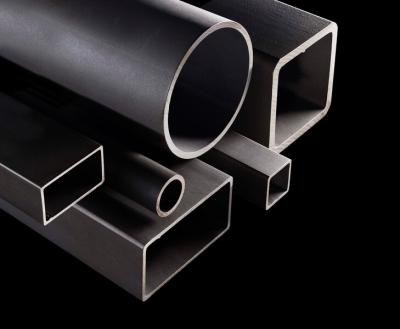
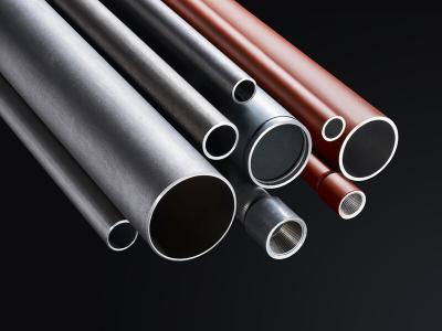
Structural hollow sections are available in a wide range of square, rectangular, circular and even elliptical shapes. From a fabrication point of view, the shape will have an effect on the cost and it is important to understand what impact the initial design decision could have on the project at a later date.
Just looking at K-joints as an example, the shape of hollow section and choice of either gap or overlap will make a difference to the fabrication cost. The cheapest solution is the RHS gap joint with the most expensive to fabricate being where a partial overlap joint is used with CHS sections, as seen in the diagram below.
Joint Design
Traditionally, the design of lattice structures is based on pin-jointed frames, with their members in tension or compression and the forces noding (meeting at a common point) at the centre of each joint. The usual practice is for the members noding on the centre line of the chord to produce a joint with no eccentricity. In reality this is rarely possible when looking at joint design as, in order to satisfy the criteria for minimum gap or overlap, some eccentricity is generally introduced.
Eccentricity is not necessarily an inconvenience for the designer, as long as this is within certain parameter limits. This ensures that the geometry of the joint in question is consistent with the empirical data used to derive the design equations. If the parameters are satisfied then the stiffness of the chord will be such that it can be assumed that any secondary moments from eccentricity are resisted by the chord and not distributed to the brace members.
Joint design is always a compromise between various conflicting requirements, but in all cases, joints must be designed to not compromise the integrity of the structure and so a thorough process of checking the integrity of all joints is always required. There are a few simple rules which can be followed to help in efficient joint design:
- The joint resistance will always be higher if the thinner member sits on and is welded to the thicker member, rather than the other way around.
- Joints with overlapping bracings will generally have a higher resistance than joints with a gap between the bracings.
- The joint resistance, for all joint and load types (except fully overlapped joints), will be increased if small thick chords rather than larger and thinner chords are used.
- Joints with a gap between the bracings have a higher resistance if the bracing to chord width ratio is as high as possible. This means large thin bracings and small thick chords.
- Joints with partially overlapping bracings have a higher resistance if both the chord and the overlapped bracing are as small and thick as possible.
- Joints with fully overlapping bracings have a higher resistance if the overlapped bracing is as small and thick as possible. In this case, the chord has no effect on the joint resistance.
- On a size for size basis, joints with circular chords will have a higher resistance than joints with rectangular chords.
- The angle between the chord and a bracing or between two bracings should be between 30° and 90°.
Checking each joint for the relevant failure modes and integrity under the design loads is often seen as complex and time-consuming, but at Tata Steel, we have produced a useful tool which can help in performing the relevant calculations. The software is more than just a calculation as it also highlights any failure modes plus indicates what is required to improve the capacity.
We always ensure that our joint design software is as up-to-date as possible, taking account of the latest learnings on joint design. This software is available free-of-charge from our technical design team.
To fully understand the details of joint design and the types of calculations required, we have also
- Published a comprehensive 72-page guide to designing joints for hollow sections. This is freely available to download from our website from this link.
- Developed a CPD which gives an insight into the design and fabrication of welded structural hollow sections - Click here to book your CPD.