


Tata Steel offer a free diaphragm design service when using RoofDek profiles – for more information contact us

*** Tata Steel offer a free diaphragm design service when using RoofDek profiles – for more information, please call +44 (0)1244 892199 or email technical.structuralproducts@tatasteeleurope.com ***
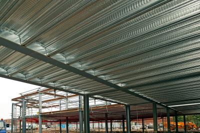
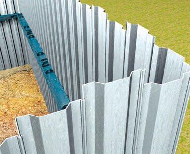
Metal Decks installed as diaphragm, or stressed skin, design allows the horizontal side wind force to be transmitted through the deck into the support frame structure. This allows the designer to remove certain cross bracing, improving the internal aesthetic view of the roof.
Any diaphragm area must have a minimum of three braced walls. Where decks are required to resist diaphragm loads, in addition to standard fixing requirements the deck must be fixed around the full perimeter, as indicated in the sketches below.
Deck directly fixed to main steelwork
Fixing to parallel members is not too difficult because these can be at the same level as the deck support beams.
Deck to support fastener positions (red arrows)
- Each arrow may signify more than one fixing.
- Fastener specification to be determined by fastener manufacturer to suit support structure.
- Shot fired pins determined by manufacturer subject to minimum flange thickness (not suitable for timber supports).
Deck to parallel beam fastener positions (green arrows)
- Perimeter screw centres will be determined from diaphragm design calculations.
Side lap fastener (blue arrows)
- Stitching centres will be determined from diaphragm design calculations.
- Stitching fastener specification to be determined by fastener manufacturer.
- Alternative rivet specification to be determined by fastener manufacturer.
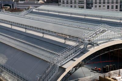
Deck fixed to purlins
When the deck is on purlins, shear connector brackets are needed to enable the connection to parallel rafters.
Deck to support fastener positions (red arrows)
- Each arrow may signify more than one fixing.
- Fastener specification to be determined by fastener manufacturer to suit support structure.
- Shot fired pins determined by manufacturer subject to minimum flange thickness (not suitable for timber supports)
Deck to parallel beam fastener positions (green arrows)
- Perimeter screw centres will be determined from diaphragm design calculations.
Side lap fasteners (blue arrows)
- Stitching centres will be determined from diaphragm design calculations.
- Stitching fastener specification to be determined by fastener manufacturer.
- Alternative rivet specification to be determined by fastener manufacturer.
Diaphragm Design
Tata Steel can provide diaphragm design calculations, carried out to Eurocode 3 for steel decks and Eurocode 9 for aluminium. Prior to any diaphragm calculation the deck must be checked for normal loads to include:- live, dead, wind suction and pressure, snow drift loads, all stated as kN/m2.
Information for diaphragm calculations comprise:-
- A dimensioned drawing indicating main support, or purlin, positions.
- An indication where braced walls are positioned, a minimum of three braced walls are required.
- The wind load acting at the perimeter, stated as a line load in kN/m.
Responsibility
The designer responsible for the overall stability of the structure should ensure the compatibility of design and details of parts and components, including stressed skin shear diaphragms. There should be no doubt as to where the responsibility for overall stability lies when some or all of the design and details are not made by the same designer.
The provider of the diaphragm calculations is not responsible for the overall stability of the structure. Responsibility for overall stability lies with the Structural Engineer responsible for the project.
The building structure design must consider how the load will be transferred between the walls and the roof deck and how the load will transfer to foundations though braced wall elements. It is essential that any diaphragm area be surrounded by at least three braced walls, that the deck is fixed down at all four edges of the diaphragm area and that edge members are continuous. Where there is one unbraced and three braced walls supporting the diaphragm area, this gives rise to a cantilever diaphragm.
Openings
Openings in decks must be trimmed or fully supported according to Tata Steel deck penetration rules. Openings totalling more than 3% of the area in each panel should not be permitted unless they conform to ECCS No.88 Clause 8.3. Openings of less than 3% of the area in each panel may be permitted without special calculation provided the total number of fasteners in each panel is not reduced.
Diaphragm deflection
An overall deflection is given, however no criteria are applied as to whether this is satisfactory or not. It is up to the building designer to define an acceptable level of deflection of the diaphragm.
Pitched roof with a ridge
A full structural connection must be made between the deck sheets on each side of a ridge. Where the deck sheets are perpendicular to the ridge, a suitable connection would be a 1.6mm galvanized steel flashing securely fixed to both sheets fixed at the frequency specified for fixings at the supports but not less than every trough of the deck.
The fixings should pass through the deck into the 1.6mm steel flashing. Where the deck sheets are parallel, a suitable connection would be a 1.2mm galvanised steel flashing securely fixed to both sheets fixed at the frequency specified for seam fixings.
Roofs of irregular shape
For convenience, the software assumes that a building is rectangular with one diaphragm area. The real building might consist of more than one diaphragm area as in the case shown below. In this case the calculations must be run for each diaphragm area separately. When a roof which is required to act as a diaphragm has an irregular plan form and/or parts of the roof at different levels it is necessary to divide the roof into zones so that each part of the building is stabilised by a rectangular diaphragm zone to resist horizontal forces applied in both the longitudinal and transverse directions.
In the design calculations each zone is then treated as a separate diaphragm. The diagram below shows a typical roof plan of such a building in which the roof is divided into zones A, B, C, and D. Zones A and C act as conventional diaphragms spanning between vertical bracings to resist both North/South and East/West loads.
Zone D resists North/South loads only and acts as a cantilever off zone A. Zone B contains a relatively high proportion of roof lights but is in fact surplus to requirements and need not be designed as a diaphragm.